

- By Sayeed Mokashi
- November 12, 2026
- 0 Comment
Nozzle Welders: Complete Guide for Pressure Vessel Fabrication
Walk through any pressure vessel shop and count the nozzles. Inlets, outlets, manways, instrument ports, drains. A single separator can carry a dozen of them, and every one is a weld that has to be made, inspected and documented before the vessel ships.
Most of the shell is easy to automate. Longitudinal and circumferential seams run in straight lines or simple circles, so a column and boom with a rotator handles them well. The nozzle is where automation gets hard. A round pipe meeting a curved shell does not produce a flat circle. It produces a saddle: a seam that rises and falls as it travels around the nozzle. On a thick wall, that saddle needs dozens of passes, and doing it by hand is where welding hours quietly pile up.
A nozzle welder exists to take that saddle off the welder’s hands. The term gets used loosely, though. Some suppliers mean a six-axis robot with a welding torch. Others mean a dedicated special-purpose machine that mounts on the nozzle and runs submerged arc welding around it. Both get sold as a “robotic nozzle welder”, and that is exactly why buyers struggle to compare quotations.
This guide fixes the vocabulary first. It then explains what a nozzle welder actually is, how it is built, why submerged arc welding dominates thick nozzle work and the handful of numbers that decide whether a machine will fit your vessels.
Contents
- 1. The Nozzle Welding Family: Table to save your time :
- 2. What a nozzle welder is (in detail)
- 3. Anatomy of a nozzle welder
- 4. Welding approaches for nozzles compared
- 5. Which approach is right for your shop floor?
- 6. Where nozzle welders are used?
- 7. Sagitta: the number that decides fit
- 8. Why big nozzles need big shells?
- 9. How to specify a nozzle welder?
- 10. Drupe Nozzle Welder specifications
- 11. Where Drupe's nozzle welder fits?
- 12. Talk to Drupe about your nozzle welding project
- 13. Frequently asked questions
- 14. Author
The Nozzle Welding Family: Table to save your time :
Most confusion in buying nozzle welding equipment comes from treating several different machines as one product. Each term below means something different and solves a different problem.
| Term | What it is | Where you'll find it |
|---|---|---|
Nozzle welderNozzle welding machine | A machine that welds a nozzle to a shell, head or drum by following the saddle-shaped intersection. | Pressure vessel, boiler and heat exchanger shops. |
SAW nozzle welder | A dedicated nozzle welder running submerged arc welding, with wire feed and flux handling built in. | Thick-wall nozzle attachment welds that need many passes. |
Robotic nozzle welding cell | A six-axis robot, usually with a positioner, programmed to weld nozzle joints with a MIG or flux-cored torch. | Mixed production where one cell handles many joint types. |
Orbital pipe welder | A head that travels around a pipe, usually for butt joints between two pipes of the same diameter. | Pipelines, process piping, tube work. |
Column and boom with rotator | A manipulator holding a welding head over a shell turning on rollers. | Long seams and circumferential seams on shells. |
Nozzle cladding system | Equipment that deposits a corrosion-resistant overlay on a nozzle bore or face. | Overlay work on nozzles for corrosive service. |
Two things are worth noting. First, an orbital welder and a nozzle welder both go “around a pipe”, but an orbital weld sits in a single plane while a nozzle weld climbs and drops as it travels. That vertical movement is the whole engineering problem. Second, a column and boom cannot do nozzle work on its own, because the nozzle axis sits at right angles to the shell axis the rotator turns about.
If you remember one line, remember this: an orbital welder goes around a circle; a nozzle welder goes around a saddle.
What a nozzle welder is (in detail)
A nozzle welder is a self-contained welding machine. It mounts on or over the nozzle, centres itself on the nozzle axis and drives the welding head around the joint pass after pass, following the saddle and placing each bead where the procedure says it should go.
Three things separate a real nozzle welder from a welding head on a rotating arm:
- It follows the saddle, not a circle. As the head travels around the nozzle, the seam rises and falls with the curvature of the shell. The machine has to coordinate rotation with vertical movement so the torch stays at the correct height and angle all the way round.
- It carries a heavy-fabrication process. Thick nozzle welds need a lot of weld metal. A SAW nozzle welder brings the wire feeder, flux delivery and usually flux recovery with it, sized for long multi-pass runs.
- It is set up around the nozzle itself. Centring and mounting determine whether a perfectly repeatable path lands on the real joint or 3 mm beside it. Alignment is part of the machine, not an afterthought.
This is why a nozzle welder is a machine, not an accessory. You are paying for coordinated saddle motion, a process package that can run for hours at high current and a mounting system that puts the path on the joint every time.
The trade-off runs the other way too. A shop that welds a handful of small nozzles a month, in mixed positions and materials, does not need any of this. A skilled welder with a good procedure will be faster to set up and cheaper to run. Buying a nozzle welder for a job a welder can do in an afternoon is just as wrong as running thick-wall nozzles by hand for years.
Anatomy of a nozzle welder
Strip any SAW nozzle welder down and you find the same building blocks, scaled to the nozzle range it is built for.
Mounting and centring. The interface between the machine and the nozzle. It locates the machine on the nozzle axis and holds it steady while the head travels and cable loads shift. Ask how alignment is set, how it is checked and how long it takes to change from one nozzle size to the next.
Rotary motion. The axis that carries the welding head around the nozzle. It sets travel speed along the seam, which is what the welding procedure actually cares about.
Contour motion. The movement that lifts and lowers the head as the saddle rises and falls. On a CNC machine, the saddle path is calculated from the nozzle and shell geometry rather than traced by hand.
Head positioning. Adjustments that set torch angle, stick-out and bead placement across the groove. In a multi-pass weld, every new pass sits in a slightly different place, so this is what turns one good bead into a full joint.
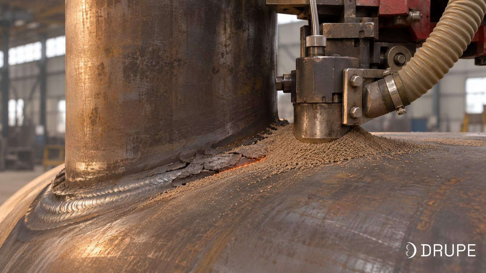
SAW head, wire feed and flux. The head feeds a continuous wire into the joint while granular flux covers the weld zone. The arc burns under the flux, out of sight. A flux hopper feeds the head. Where included, a recovery unit collects unfused flux for reuse.
Power source. The SAW power source supplies the high current that gives the process its deposition rate. Its interface with the machine controller decides which parameters can be set and logged from the pendant.
Controls and pendant. Servo drives, a motion controller and an operator pendant. This is where joint geometry is entered, the path is checked and parameters are stored so the next identical nozzle starts from a proven setup.
Any quotation that lists the nozzle OD range but not the minimum shell diameter and the sagitta limit is leaving out the numbers that decide whether the machine fits your vessels.
Welding approaches for nozzles compared
Manual stick (SMAW)
Welder runs covered electrodes around the joint by hand.
- Deposition
- Low
- Wall thickness
- Any, but slow on thick walls
- Position
- All positions
- Best for
- Small nozzles, low volume, repairs, site work
Trade-offsHours per nozzle on thick walls; result depends on the individual welder.
Semi-automatic MIG or flux-cored
Welder guides a wire-fed torch by hand.
- Deposition
- Low to medium
- Wall thickness
- Thin to medium
- Position
- Most positions
- Best for
- Medium-wall nozzles, mixed work
Trade-offsStill manual on a saddle path; fatigue on long multi-pass joints.
Robotic MIG or flux-cored cell
Six-axis robot follows a programmed path, often with a positioner.
- Deposition
- Medium
- Wall thickness
- Thin to medium
- Position
- Most, with programming
- Best for
- High mix of joint types in one cell
Trade-offsProgramming time per part; reach and torch angle limits around large shells.
Dedicated SAW nozzle welder
Machine mounts on the nozzle and runs submerged arc around the saddle.
- Deposition
- High
- Wall thickness
- Medium to very thick
- Position
- Near-flat only, flux must stay in place
- Best for
- Thick-wall nozzles in repeat families
Trade-offsNeeds the nozzle axis roughly vertical; limited by its OD, shell and sagitta envelope.
Which approach is right for your shop floor?
Few nozzles, small diameters, mixed positions and materials. Manual or semi-automatic welding
Repeat nozzle families, thick walls, nozzle axis can be set vertical. Dedicated SAW nozzle welder
High mix of joints across many parts, thinner walls, varied orientations. Robotic welding cell
Inclined, offset or hillside nozzles outside a standard envelope. Engineered solution, proven on a trial joint first
For pressure vessel, boiler and heavy process equipment shops welding thick carbon steel nozzles in volume, the answer is almost always a dedicated SAW nozzle welder. It is the only approach that combines the deposition rate thick walls demand with a motion system built around the saddle.
If your nozzles are part of a wider robotic welding plan on large structures, our gantry systems guide and linear track guide explain how robots get the reach they need.
Where nozzle welders are used?
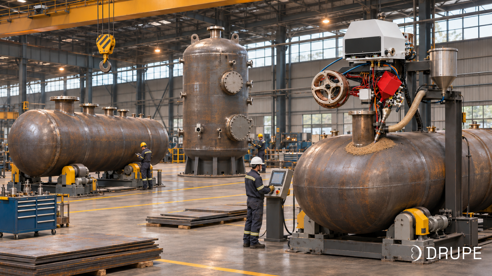
The same machine shows up across very different equipment. The weld detail, wall thickness and access decide whether a given nozzle suits it, not the industry label.
1. Pressure vessels and process equipment
The core application. Columns, reactors, separators, accumulators and storage vessels carry repeat nozzle families on thick shells and heads, which is exactly where setup becomes predictable and SAW deposition pays off. Closely spaced nozzles, reinforcing pads and internals need checking during the access review. See our pressure vessel fabrication solutions.
[IMG-4: Pressure vessel shop scene]
2. Boilers and power equipment
Boiler drums and headers carry large numbers of nozzles on very thick walls, often in alloy steels with demanding preheat requirements. Large drum nozzles suit SAW well. Small header stubs usually fall below the working range of a large nozzle welder and need a different solution.
3. Heat exchangers
Shell-side nozzles on heat exchangers are a good fit when they repeat across a product family. Tube-to-tubesheet welding is a completely different application with its own orbital tooling.
4. Storage tanks, oil and gas separators
Tank connections, separators and slug catchers carry large nozzles and manways. Many suit SAW; some, because of orientation or wall thickness, are better welded another way. A single project often contains both.
5. Nozzle cladding and overlay
Corrosive service may need weld overlay on the nozzle bore or face. That is a cladding job with its own process and tooling, not an attachment weld, so specify it separately.
Sagitta: the number that decides fit
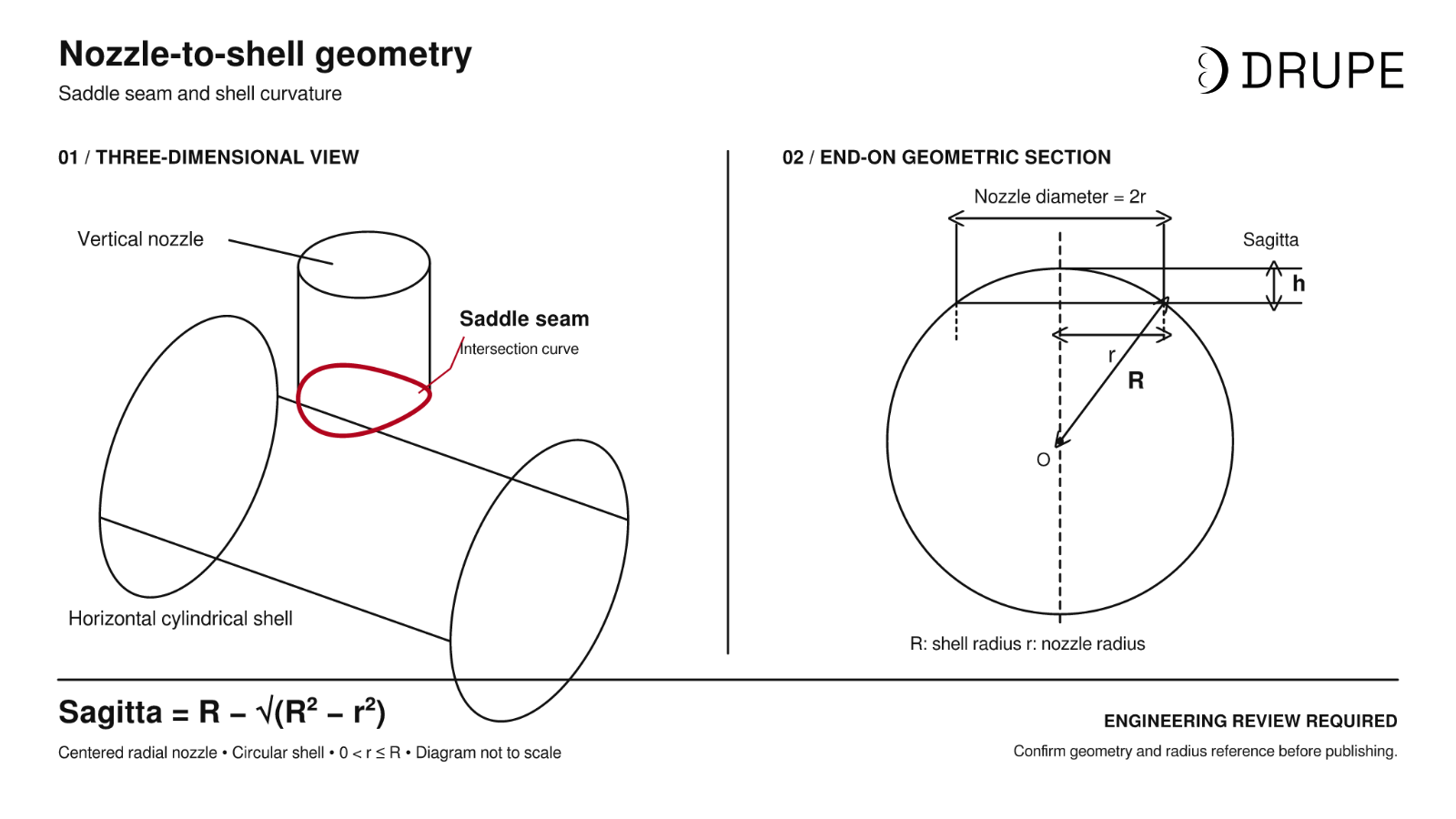
Nozzle OD is the first number buyers ask about. Sagitta is the one that usually decides whether a machine can actually weld the joint.
What it is. When a nozzle of radius r meets a shell of radius R at right angles, the seam rises and falls as it goes around. The height difference between the lowest and highest points of that saddle is the sagitta:
Sagitta = R – √(R² – r²)
A nozzle welder can only lift and lower its head so far. If your joint’s sagitta exceeds the machine’s limit, it cannot follow the seam, however comfortably the nozzle sits inside the advertised OD range.
Why diameter alone misleads. Sagitta depends on the ratio of nozzle to shell. The same 800 mm nozzle produces a very different saddle on different shells:
| Nozzle OD | Shell diameter | Sagitta | Against a 150 mm limit |
|---|---|---|---|
| 300 mm | 1,200 mm | 19 mm | Well within |
| 500 mm | 1,200 mm | 55 mm | Well within |
| 800 mm | 1,200 mm | 153 mm | Just over the limit |
| 800 mm | 2,000 mm | 84 mm | Within |
| 1,200 mm | 1,400 mm | 339 mm | More than twice the limit |
| 1,200 mm | 3,000 mm | 125 mm | Within |
Red line marks a 150 mm sagitta limit.
Turn it around and you get the smallest shell a 150 mm sagitta limit can handle for each nozzle size:
| Nozzle OD | Smallest shell diameter at 150 mm sagitta | Relative shell size |
|---|---|---|
| 300 mm | 300 mm (other limits govern first) | |
| 500 mm | about 570 mm | |
| 800 mm | about 1,220 mm | |
| 1,000 mm | about 1,820 mm | |
| 1,200 mm | about 2,550 mm |
Why big nozzles need big shells?
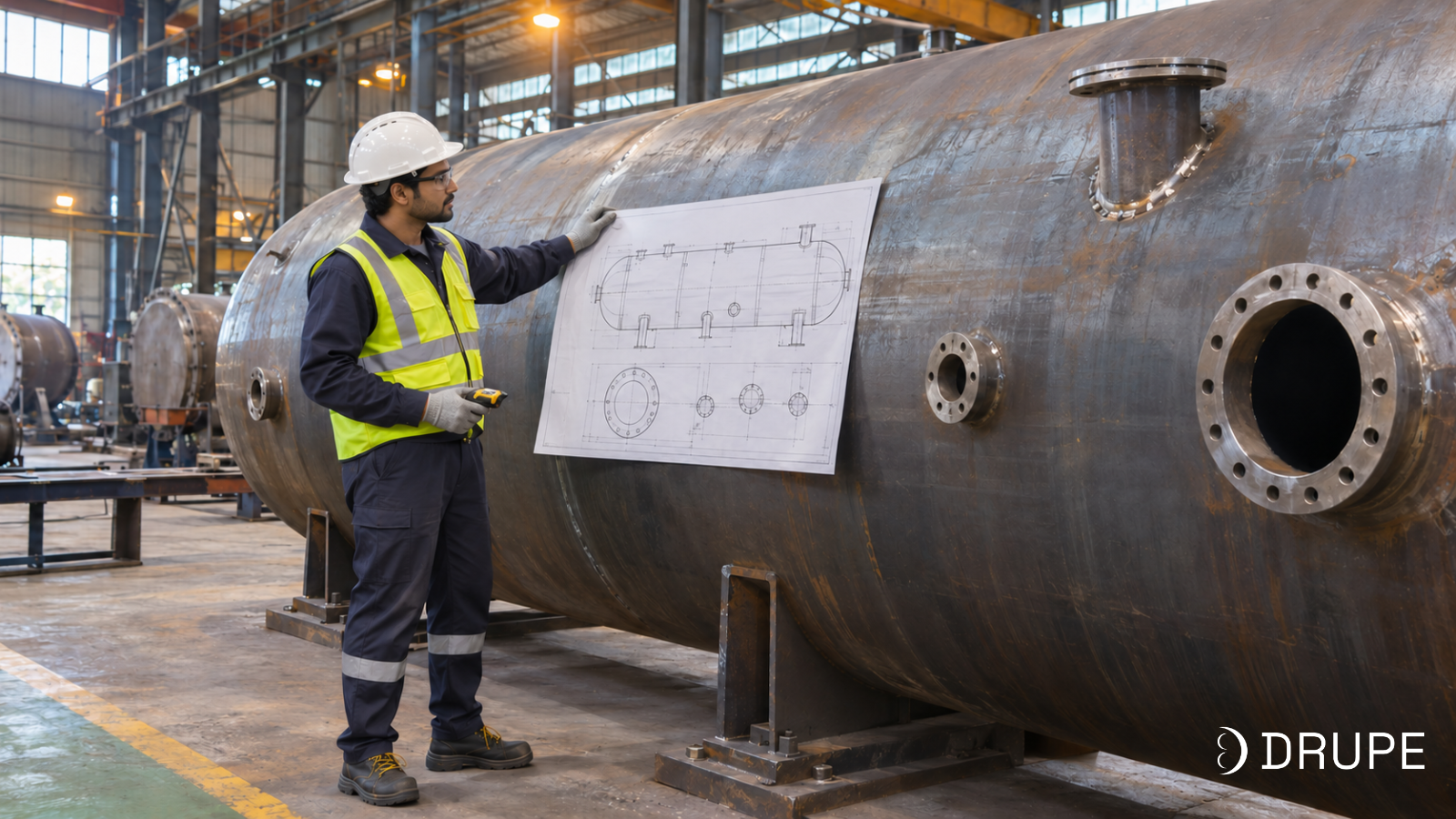
Large nozzle capacity and small shell clearance are not available at the same time. A 1,200 mm nozzle on a 1,400 mm shell has a saddle more than twice as deep as a 150 mm limit allows. The same nozzle on a shell above roughly 2.5 m is comfortably inside it.
The quiet rule: check sagitta for your largest nozzle on your smallest shell. That single pair tells you more about fit than any line in a brochure. Inclined nozzles, offset (hillside) nozzles and nozzles on dished heads change the geometry again and need their own review.
These figures use the standard geometric definition for a radial nozzle on a cylindrical shell. Confirm the exact definition and reference diameters with your supplier.
Where the hours actually go?
SAW is chosen for nozzles because of deposition, so it helps to see what that means on a real joint.
A worked example. Take a 600 mm OD nozzle with a groove cross-section of about 1,000 mm², roughly what a single-bevel preparation on a 40 mm wall needs. The seam is just under 1.9 m long, so the joint holds about 15 kg of weld metal.
- At an assumed 2 kg/h for manual welding in position, that is around 7.5 hours of arc time.
- At 6.5 kg/h for single-wire SAW, it is around 2.3 hours.
These are illustrative assumptions, not guaranteed figures. Your preparation, material and procedure set the real numbers.
Arc time is not cycle time
The arc is only part of the job. Mounting, centring, slag removal, interpass temperature control and inspection all add time, and a nozzle that needs repair costs more than all of them. A machine that cuts arc time by two-thirds but takes an hour to set up on every new nozzle will disappoint on a high-mix floor.
The quiet rule in vessel fabrication: buy on time per accepted nozzle, not on arc time. Measure setup, welding, interpass work, inspection and repair for your current method, then compare it with a trial on your own joint.
For a simple payback estimate, divide the installed investment by the annual value of welding hours released and rework avoided, less the extra running and maintenance cost. Count extra output only where you can actually sell it.
What SAW asks in return?
SAW needs the flux to stay on the joint and the molten pool to stay in place. That means welding close to flat, so the nozzle axis is normally set vertical with the vessel positioned to suit. Steep saddles on large nozzle-to-shell ratios make flux retention harder, which is another reason sagitta matters. Wire and flux also have to match the material and required properties; a combination proven on one carbon steel vessel does not transfer automatically to another material.
How to specify a nozzle welder?
If you give a supplier the items below, you will get a quotation that fits your vessels. If you give them “nozzle OD” and nothing else, you will get the catalogue machine closest to that number and a long back-and-forth afterwards.
| Item | Why it matters |
|---|---|
| Joint geometry | |
1Nozzle OD range, smallest and largest | Sets the machine envelope and whether an extension is needed. Small nozzles limit head space; large ones limit travel. |
2Shell diameter range and head profiles | Together with nozzle OD, sets the sagitta and internal access. |
3Nozzle and shell wall thickness, weld preparation | Sets groove volume, number of passes and access as the weld fills. |
4Nozzle type and orientation (set-on, set-in, radial, inclined, offset) | Changes the path geometry and whether a standard machine applies at all. |
5Inside, outside or both-side welding | Decides minimum shell ID for internal work and how the machine is loaded. |
| Welding process | |
6Material, wire and flux, existing WPS | Decides process settings and whether a qualified procedure already exists. |
7Preheat and interpass requirements | Affects cycle time and how the machine and operator work around a hot joint. |
| Volume and integration | |
8Nozzles per vessel and vessels per year | Sets the business case and how much setup speed matters. |
9Existing SAW power source | Decides integration scope and what can be logged from the pendant. |
10Traceability and data logging needs | Decides which parameters must be recorded and how they are exported. |
Factors that often get missed
Neighbouring features. Reinforcing pads, lifting lugs and closely spaced nozzles can block the head long before the nozzle OD becomes a problem. Check the full nozzle orientation drawing, not just the nozzle schedule.
Flux on steep saddles. The larger the nozzle relative to the shell, the steeper the flanks of the saddle and the harder it is to keep flux on the joint. If your largest nozzles sit on your smallest shells, trial that combination first.
Heat. Thick alloy nozzles may need high preheat held for hours. Ask how the head, cables and flux hoses cope with sustained heat, and how operators work around it.
Slag removal. Multi-pass SAW leaves slag after every pass. Clarify whether cleaning is manual between passes and build that time into the cycle.
Fit-up is half the weld
A nozzle welder repeats its path perfectly. It cannot fix a nozzle that is off-centre, out of square or fitted with an uneven root gap. Consistent opening preparation, nozzle squareness and tacking are what let the machine run pass after pass without intervention. Poor fit-up is the most common reason an automatic nozzle weld needs an operator’s hand during the cycle.
Automation does not qualify your procedure
For code work, you still need a qualified welding procedure and qualified welding operators. ASME Section IX covers procedure and personnel qualification where it applies. Buying an automated machine does not by itself make a weld code-compliant. Agree the trial joint and its acceptance criteria before the machine trial, not after.
Drupe Nozzle Welder specifications
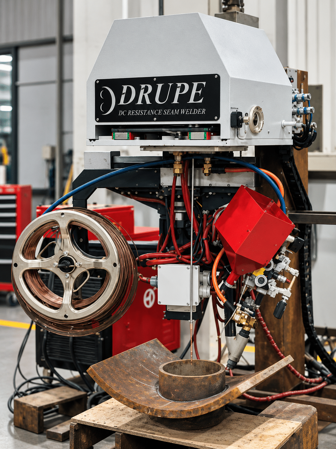
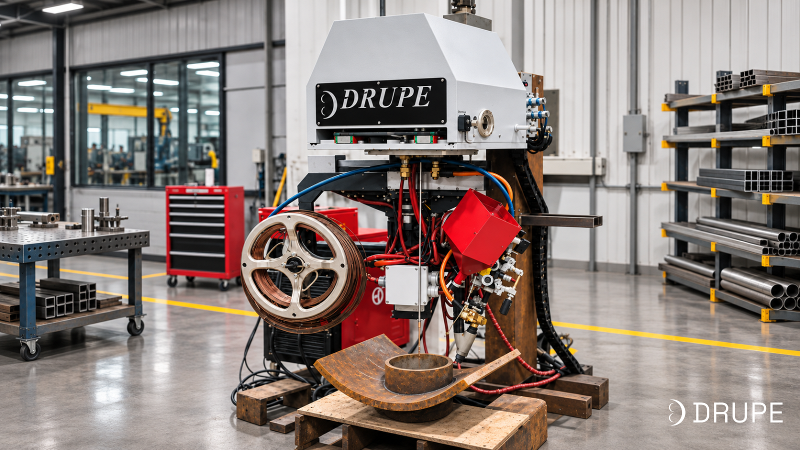
Drupe SAW nozzle welder
Dedicated SPM, not an articulated robot| Capacity | Standard | With extension |
|---|---|---|
| Nozzle OD | 100-800 mm | Up to 1,200 mm |
| Minimum shell ID | 1,200 mm | 1,400 mm |
| Maximum nozzle thickness | 200 mm | |
| Maximum sagitta | 150 mm | |
| Process and control | ||
| Welding process | Submerged arc welding (SAW) | |
| Control | CNC saddle path, servo motors, motion-control PLC | |
| Operator interface | 7 inch HMI touchscreen teach pendant | |
| Features and options | ||
| Features | Data loggingStitch weldingMulti-brand power source integration | |
| Option | Arc voltage control (AVC) | |
Each limit applies on its own; they are not all reachable on one joint at the same time. The largest nozzle sizes need shells well above the minimum ID. Send your nozzle and shell drawings and Drupe will confirm fit for your actual joints.
Check fit for your jointsWhere Drupe's nozzle welder fits?
Drupe builds the nozzle welder as part of a wider welding automation range, designed and manufactured by the same team at MIDC Taloja.
SAW nozzle welder. For thick-wall nozzle attachment welds on pressure vessels, boilers, heat exchangers and process equipment, from 100 mm nozzles upward.
Welding automation. Column and boom manipulators, welding rotators and seam welding systems for the long and circumferential seams on the same vessels.
Gantries, linear tracks and robotic cells. Motion systems and complete cells for welding and cutting large structures.
Special-purpose machines. Custom solutions where a standard envelope does not fit, built on the same in-house mechanics and controls.
Why that end-to-end capability matters
Most nozzle welding problems are not machine problems in isolation. They sit inside a shop: how the vessel is positioned, how the nozzle is fitted, which power source is already on the floor and how the procedure was qualified. Drupe designs the mechanics, controls and software in-house, which means the machine can be matched to your vessels and process rather than the other way round, and any issue after commissioning is handled by the people who built it.
Drupe has designed and built industrial automation since 1992. If you are not sure whether your nozzles need a dedicated nozzle welder, a robotic cell or a custom machine, that conversation is the right place to start.
Talk to Drupe about your nozzle welding project
Send us your nozzle and shell drawings, material, weld preparation and the number of nozzles you weld each year. Include your welding procedure if you have one. Our team will tell you whether your joints fit a standard machine, what extension or option they need and what a trial on your joint should prove.
Request an application review or write to sales@drupeengg.com.
Frequently asked questions
A nozzle welder is a machine that welds a nozzle to a vessel shell, head or drum. It moves the welding head around the joint while following the saddle-shaped rise and fall of the seam, so each pass is placed the same way every time.
Not necessarily. Some systems use a six-axis robot with a MIG or flux-cored torch. Most thick-wall nozzle work uses a dedicated SAW nozzle welder that mounts on the nozzle. Drupe’s nozzle welder is a dedicated CNC machine.
Thick nozzle joints need a lot of weld metal, and SAW deposits it several times faster than manual processes under mechanised control. The trade-off is that SAW needs a near-flat welding position, so the nozzle axis is usually set vertical.
Sagitta is the height difference between the lowest and highest points of the saddle-shaped seam. It depends on the nozzle and shell diameters together. If it exceeds the machine’s limit, the machine cannot follow the joint even when the nozzle OD is within range.
Nozzle OD of 100-800 mm as standard and up to 1,200 mm with an extension, on shells from 1,200 mm ID, with a 150 mm sagitta limit. Large nozzles need correspondingly large shells, so Drupe confirms fit from your drawings.
Yes, when the shell is large enough for the machine to enter, mount and travel. Drupe’s machine needs a minimum shell ID of 1,200 mm without the extension and 1,400 mm with it.
It depends on the nozzle range, extension, power source, flux handling and commissioning scope. Send your drawings and annual nozzle volume for a quotation built on your joints.