

- By Rathish Johnson
- November 17, 2026
- 0 Comment
Linear Slides: The Complete Guide to Types, Selection and Specification (2027)
The axis was specified at 40 kg. The payload weighed 12. Eight months later the bearing blocks had gone notchy, the repeatability was nowhere near the datasheet and nobody on the floor could explain why.
The payload was never the problem. The 600 mm arm it sat on was.
Moving one thing in a straight line, to a known position, as many times as the cycle demands, is the most common job in industrial machinery. It is also the job most often built from loose parts instead of bought as a finished unit. Walk through any machine building shop and you will find it half assembled on every second bench: a pick and place head still waiting for its Z axis, a dispensing station bolted down but not yet aligned, a test rig where a rail has been clamped to a fabricated plate and someone is chasing 0.3 mm of parallelism with a dial gauge and a hammer.
Cost leaks out of that choice quietly. Count what goes into one axis built from parts: a rail, a ball screw, two support units, a locknut, a coupling, a motor mount and a machined carriage plate. Eight part numbers, eight lead times and an alignment problem that lands on whoever assembles it. A linear slide collapses all of it into one part number with a datasheet attached.
The naming does not help either. One supplier’s linear slide is a 60 mm cross roller stage. Another’s is a 4 metre belt driven axis carrying 30 kg. Catalogues use linear slide, linear slider, linear module, linear actuator and single axis robot for products that are sometimes identical and sometimes nothing alike, which is how a buyer ends up comparing three quotations for three different things.
This guide covers the subject end to end: the vocabulary, what a linear slide actually is, the six guide technologies and where each one belongs, how the drive choice shapes everything downstream, how to read a datasheet, the two limits that catch people out, how slides stack into multi axis builds, how they fail in service and how to write a specification that comes back quoted correctly.
Contents
- 1. Linear slide, linear rail or linear actuator? What each term means?
- 2. What is a linear slide?
- 3. What is inside a linear slide?
- 4. Types of linear slide: the six guide technologies
- 5. How to pick between them?
- 6. Ball screw or belt? How linear slides are driven?
- 7. What the drive actually decides?
- 8. How to choose between a ball screw and a belt slide?
- 9. Linear slide accuracy: how to read the datasheet?
- 10. Manual, motorised and multi axis linear slides
- 11. Where are linear slides used?
- 12. Moment load: why payload in kilograms is not enough?
- 13. Why do ball screw slides stop at about one metre of stroke?
- 14. Linear slide life, lubrication and failure modes
- 15. How to specify a linear slide: a 13 point checklist
- 16. Drupe linear slide specifications
- 17. Where Drupe's linear slide range fits
- 18. Talk to Drupe about your axis
- 19. Frequently asked questions
- 20. Author
Linear slide, linear rail or linear actuator? What each term means?
Treating linear motion as one product is where most buying confusion starts. Each term below describes something different, sits at a different price point and is usually sold by a different kind of supplier.
| Term | What it is | Where you'll find it |
|---|---|---|
Linear raillinear guide | A hardened steel rail with recirculating ball or roller blocks. A component, bought by the metre. | Inside almost every machine axis ever built. |
Linear bearing block | The carriage that runs on the rail, chosen by load rating and preload class. | Bolted to a plate to make an axis. |
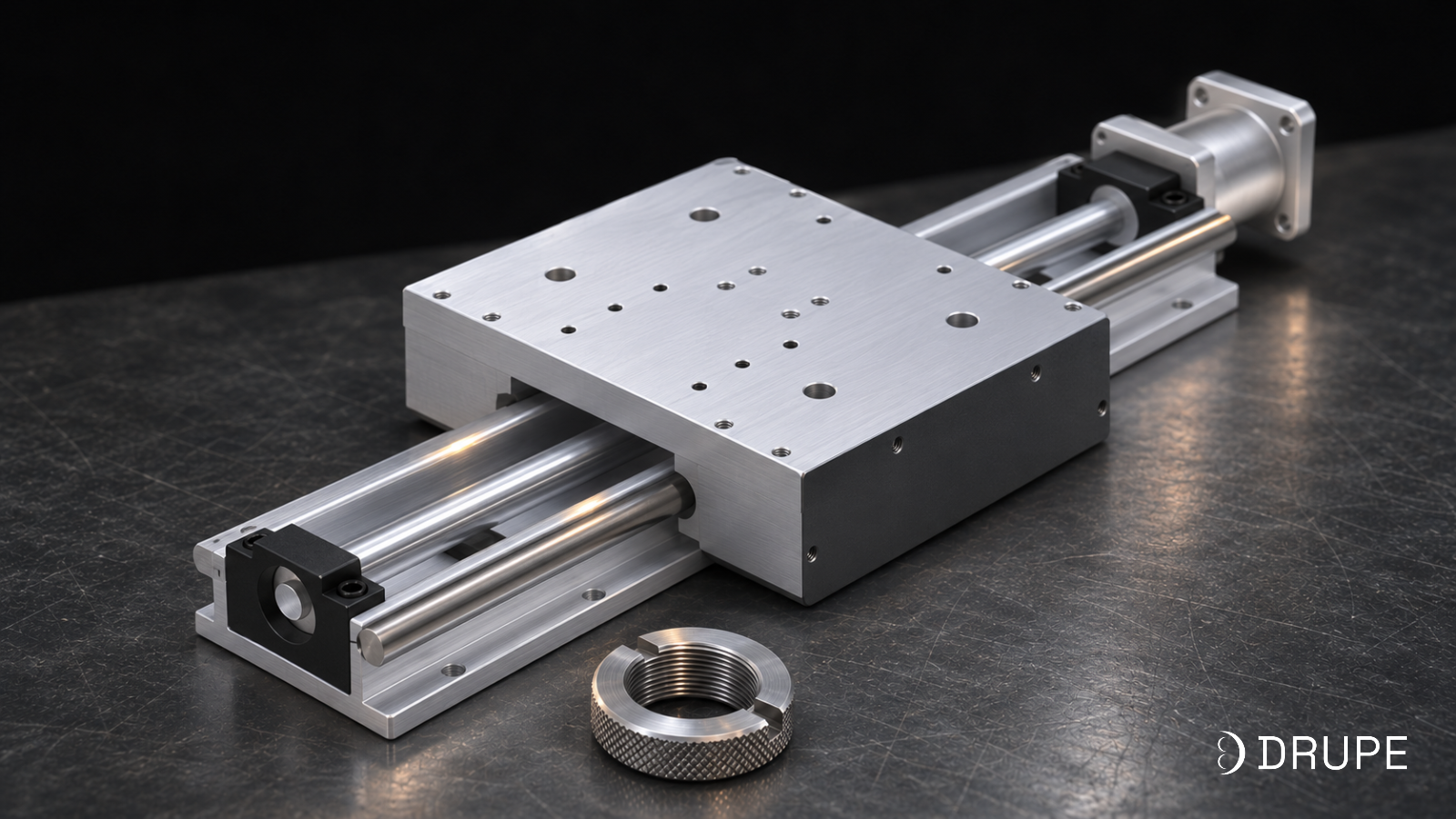
Linear slidelinear slider, linear module | A pre assembled axis: base, rails, carriage and drive, supplied aligned, with a stated accuracy. | Machine tools, SPMs, assembly stations, pick and place heads. |
Linear actuator | A motorised push or pull device. Force first, accuracy second. | Clamping, lifting, pressing, feed advance. |
Single axis robot | A slide sold with its own drive and controller, programmed by position rather than wired as an axis. | Electronics assembly, lab automation, dispensing. |
Linear stage | A short stroke, very high precision slide, often manual or micrometer driven. | Metrology, optics, inspection benches. |
XY or XYZ assembly | Two or three slides at right angles, giving a flat or box shaped work envelope. | Dispensing, inspection, small part handling, cutting heads. |
Linear track | A heavy duty motion machine: welded steel base, servo drive, controller interface and safety. | Robot 7th axes, cutting gantries, welding manipulators. |
Three distinctions in that table do most of the work.
A rail is a part. A slide is a product. Open up a slide unit and the rails inside it are often the same rails you could have bought yourself. What the price covers is the base holding them parallel, a drive sized to match them and the fact that somebody has already aligned the whole thing and measured what came out.
Slide and actuator get swapped freely, and should not be. Look at what the specification leads with. Accuracy and repeatability at the top means a slide. Force and stroke at the top means an actuator. A datasheet quoting thrust in newtons with no repeatability figure anywhere is describing an actuator, whatever the heading says.
A slide is not a small linear track. They sit at opposite ends of the same family. You design a slide into your machine. You bolt a track to the floor and wire it to a robot or a CNC. If the real question is how to move a robot across a cell, the linear track guide answers it better than this one will.
One line to carry away: a linear rail is a bearing, a linear slide is an axis and a linear track is a machine.
What is a linear slide?
A linear slide is a complete linear axis supplied as a single unit. Bolt it to your frame, connect a motor and a drive, and it will carry a payload to a commanded position within a stated tolerance, every cycle, for a stated life.
So what separates a slide unit from two rails screwed to a fabricated plate? Three things.
- Geometry comes from the base, not from your fabrication. The rails sit on a machined aluminium extrusion or a steel body, against a reference edge cut after the body was stress relieved. Parallelism between the two rails is set in the factory and measured there. On a fabricated plate, parallelism is whatever the person with the dial gauge achieved that morning.
- The drive is already matched to the guides. Screw or belt, it has been sized against the same load the guides carry, with correct support units at both ends and preload already set. One engineering decision replaces five separate purchase decisions that all have to agree with each other.
- It arrives with numbers you can design against. Repeatability, positioning accuracy, payload, permissible moment and rated life are published. All of them go into your machine tolerance stack before any metal is cut. An axis built from parts has no such numbers until it exists and somebody measures it.
Put plainly, you are buying a tolerance you did not have to create. Not the aluminium, and not the rails.
The argument runs the other way too. Where the axis is unusual, very heavy, very long or has to be designed around structure that already exists, a slide unit forces your machine to fit the catalogue instead of the reverse. A press feed carrying 400 kg is not a slide job. Neither is a 12 metre welding runway. Those are linear tracks or special purpose machines, and calling them slides only delays the right conversation.
What is inside a linear slide?
Strip any slide unit down and the same components appear, scaled to the stroke and the load it was built for.
Body or base. Extruded aluminium on light and medium slides, steel where rigidity or load demands it. The body carries the rails, absorbs the reaction from the drive and presents the mounting face to your machine. Whatever straightness it holds over its full length becomes the ceiling for every accuracy figure printed on the datasheet.
Guide rails and blocks. Two parallel profile rails with recirculating ball blocks in most designs, or one wide rail with two blocks on compact units. Moment load is resisted by the spacing between those blocks, which explains why two short slides stacked into an XY often behave worse than a single slide with a long carriage.
Drive. Ball screw, toothed belt, occasionally rack and pinion. No other single choice does more to set stroke, speed, accuracy, thrust and price, so it gets a section of its own below.
Carriage or table. The machined plate your payload bolts onto, carrying the bearing blocks, the ball nut or belt clamp and a tapped mounting pattern. Check that pattern early. An adapter plate added later pushes your payload further from the rail and quietly raises the moment.
Support units. Housings that hold each end of the ball screw. Axial load goes through an angular contact bearing set at the fixed end. The free end takes radial load only and leaves room for thermal growth. Drupe supplies BK and BF rectangular units for shafts from 10 to 40 mm, with FK and FF flange mounted equivalents.
Locknut. A small, cheap part that holds bearing preload at the fixed end, and the single most common reason an axis loses accuracy after a few months of service. Once that preload relaxes, axial play appears and the repeatability figure is gone no matter what grade the screw is.
Motor interface. A coupling and a motor mount, with a gearbox where the inertia ratio calls for one. Get the ratio wrong and you get a tuning problem that presents as a mechanical fault, which is how commissioning loses a week.
Clamps, brakes and stops. A rail clamp holds the carriage at a stop so the drive is not fighting the load all shift. Vertical axes need a brake or a counterbalance, because a ball screw with a long lead back drives under gravity the instant power is removed.
Covers and lubrication. Bellows, strip covers or a sealed profile keep dust and swarf off the raceways, with a grease point or a central lubrication connection to reach them. None of this is optional near welding or cutting. Spatter will ruin an unprotected raceway long before any load does.
Watch for datasheets that give stroke, speed and payload but never name the guide size, the screw grade, the permissible moment or the rated life. Those four decide whether the slide survives your duty cycle, and leaving them out is rarely an accident.
Types of linear slide: the six guide technologies
The drive gets the attention, but the guide comes first. Six bearing technologies appear in linear slides and none of them substitutes for another. Rigidity, friction, contamination tolerance and cost all follow from this choice, and in practice the environment makes it for you.
| Guide type | Character | Where it belongs |
|---|---|---|
Profile rail, recirculating balls | High rigidity, low friction, needs seals and wipers. | The default on almost every motorised slide. |
Profile rail, rollers | Line contact instead of point contact, roughly twice the stiffness. | Heavy load, machine tool axes. |
Crossed roller | Very rigid for its size, very low friction, no recirculation so stroke is limited. | Short stroke precision stages, metrology, optics. |
Dovetail | Plain sliding surfaces, high damping, high friction, very dirt tolerant. | Manual slides, cutting and grinding, shock and chatter. |
Round shaft, ball bushing | Low to medium rigidity, tolerates misalignment, low cost. | Light handling and simple transfer. |
Plain polymer bush | Low rigidity, no grease at all, survives washdown. | Food, packaging, wet or abrasive lines. |
Air bearing | No mechanical contact, effectively zero friction, needs clean dry air. | Semiconductor, flat panel, ultra precision metrology. |
How to pick between them?
Start at profile rail with recirculating balls. For the large majority of motorised industrial slides this is simply the right answer, which is why most slide units are built on it. Everything that follows is a reason to move away from it.
Switch to rollers when rigidity is what binds. Line contact rather than point contact roughly doubles stiffness inside the same envelope. Worth paying for whenever the process pushes back hard.
Switch to crossed roller for short stroke and severe accuracy. Under roughly 150 mm of travel in a clean environment, a crossed roller stage beats a recirculating one. Nothing recirculates, so the small cyclic variation that limits smoothness at very low speed never appears.
Switch to dovetail where there is chatter, shock or grit. Plain sliding surfaces damp vibration in a way rolling elements cannot, and they shrug off contamination that would wreck a raceway. Friction is the price, which is why dovetails stay manual or low duty.
Switch to polymer bush when the grease itself is the problem. Washdown lines, food contact, abrasive dust. Accuracy and load capacity go, and what you get back is a bearing that does not care about any of it.
One mistake worth naming: picking a crossed roller or air bearing slide for a shop floor because the accuracy figure looked good on paper. Both want conditions most factories cannot provide, and both fail quickly once they do not get them.
Ball screw or belt? How linear slides are driven?
For a slide unit the decision comes down to ball screw against belt. The other two sit in the table because catalogues shelve them next to slides and buyers confuse them with slides.
| Drive | Repeatability | Stroke and speed | Best for |
|---|---|---|---|
| Ball screw | plus or minus 0.01 to 0.02 mm | 50 to about 1,000 mm, low to medium speed | Positioning, measurement, assembly, pressing, vertical axes |
| Toothed belt | plus or minus 0.05 to 0.1 mm | 100 to about 4,000 mm, several metres per second | Transfer, loading, gantry axes, long reach handling |
| Rack and pinion | plus or minus 0.05 to 0.1 mm | Effectively unlimited, medium to high speed | Long travel and heavy load, once you have left slide territory |
| Linear motor | Below plus or minus 0.005 mm | Short to medium, very high speed | Semiconductor, flat panel, inspection |
How each one works, and what it costs you. A ball screw turns a ground screw inside a recirculating ball nut, which is where accuracy and thrust come from, though critical speed caps length and speed together and the cost per millimetre of stroke runs high. A toothed belt is driven by a pulley at one end and clamped to the carriage, cheap across distance, but it stretches under load and over time, settles at the stop and makes a poor vertical axis without a brake. Rack and pinion needs preload or a dual pinion to control backlash plus continuous lubrication, and by then you are specifying a linear track rather than a slide. A linear motor is expensive, intolerant of contamination and heat, and gives a poor force to cost ratio under industrial loads.
What the drive actually decides?
Thrust. Motor torque gets multiplied mechanically by a ball screw. A 5 mm lead turns a modest servo into a few hundred newtons at the carriage. No belt will do that, so an axis that has to push, clamp, press or lift has already made this decision for you.
Back driving. Ball screws are efficient, and efficiency means they run backwards under load. Belts are worse. Nothing here self locks, so every vertical slide needs a motor brake or a counterbalance. Put it in the specification rather than discovering it during installation.
Settling. Energy gets stored in a belt and released at the end of a fast move, so the carriage oscillates briefly before it settles. Across a 50 move per minute cycle, that settling can eat more time than the belt saved in travel. Ask for the settling time, not just the top speed.
Stiffness. How far the axis deflects when the process pushes back comes down to axial stiffness at the carriage. A ball screw is roughly an order of magnitude stiffer than a belt of similar size. Anything that cuts, presses or holds position against force is decided on this number alone.
How to choose between a ball screw and a belt slide?
Thrust. Motor torque gets multiplied mechanically by a ball screw. A 5 mm lead turns a modest servo into a few hundred newtons at the carriage. No belt will do that, so an axis that has to push, clamp, press or lift has already made this decision for you.
Back driving. Ball screws are efficient, and efficiency means they run backwards under load. Belts are worse. Nothing here self locks, so every vertical slide needs a motor brake or a counterbalance. Put it in the specification rather than discovering it during installation.
Settling. Energy gets stored in a belt and released at the end of a fast move, so the carriage oscillates briefly before it settles. Across a 50 move per minute cycle, that settling can eat more time than the belt saved in travel. Ask for the settling time, not just the top speed.
Stiffness. How far the axis deflects when the process pushes back comes down to axial stiffness at the carriage. A ball screw is roughly an order of magnitude stiffer than a belt of similar size. Anything that cuts, presses or holds position against force is decided on this number alone.
Linear slide accuracy: how to read the datasheet?
Precision on a linear slide is described by five numbers. They sound alike, buyers mix them up constantly and each one tells you something different.
Positioning accuracy is how close the carriage gets to the absolute coordinate you commanded. Body straightness, screw lead error and any backlash in the drive train all land inside it. It is always the worst of the five, and the one most often missing from a datasheet.
Repeatability is how close the carriage returns to the same taught position over many cycles. It beats absolute accuracy almost every time, because it does not care whether the beam is straight, only whether the carriage comes back to where it was. For machines that work to taught positions rather than coordinates, this is the number to buy on.
Straightness and flatness of travel describe how far the carriage wanders off a perfect line as it moves, horizontally and vertically. Cutting, dispensing and measuring paths care about this more than about absolute coordinates.
Backlash is lost motion on reversal. A preloaded ball nut has effectively none. Wear, a loose coupling or a relaxed locknut all introduce it, which makes backlash a maintenance symptom far more often than a purchase specification.
Resolution is the smallest increment the control system can command. That is an electronics figure, not a mechanical one, and quoting it as accuracy is the oldest trick in the catalogue. One micron of resolution alongside 50 microns of repeatability gives you a 50 micron slide.
Preload, and what it costs you
Preload means deliberate interference built into the bearing blocks and the ball nut so that no clearance exists anywhere. Push it up and rigidity rises while lost motion falls. Friction, heat and wear rise with it.
Manual, motorised and multi axis linear slides
Add a servo or stepper, a drive, feedback and a controller interface and the slide becomes motorised. Name the motor brand early, because mount, coupling and inertia ratio all follow from it, and because most machine builders have already standardised on one brand for spares and training.
A single axis robot is a motorised slide that arrives with its own drive and controller, programmed by entering positions rather than wired in as an axis of your control system. Commissioning is quicker. Integration is harder. Good for standalone stations, awkward inside a machine whose PLC is already running coordinated motion.
Stacking slides into two and three axes
Real work rarely happens in one direction, so single axes get combined into XY and XYZ builds. Three arrangements cover most of it.
Cantilever XY. The Y slide bolts on top of the X carriage and the payload hangs off the end. Cheapest, simplest, smallest footprint. The Y axis and everything on it become moment load on X, and that moment grows as Y extends. Acceptable for light payloads over short reach.
Gantry XY. The Y beam rides on two parallel X slides, one at each end. Supporting the load at both ends drops the moment on each X carriage sharply and stiffens the whole structure. It costs more, takes more floor and needs the two X axes synchronised mechanically or electronically. Where span and payload are both real, this is the answer. Spans running into metres belong in the gantry systems guide.
XYZ. Either arrangement with a Z axis added. Z is almost always vertical, so ball screw and a brake, and the whole Z assembly becomes permanent payload on everything beneath it.
The stacking penalty. Each axis you stack carries everything above it, including the dead weight of the slides themselves. A 10 kg payload on a three axis build can present 35 kg to the bottom axis once the Y slide, the Z slide, the motors and the brackets are counted. Size from the bottom up and count the slides as payload, not just the part.
Accuracy stacks too, though not by simple addition. Errors in X, Y and Z combine at the tool point, and cantilever arrangements amplify angular error with distance: 0.01 degrees of pitch on the X carriage becomes 0.09 mm of error 500 mm out along the Y arm. Drupe quotes plus or minus 0.05 to plus or minus 0.1 mm repeatability on one, two and three axis gantries in medium and heavy duty, confirmed against the actual configuration at quotation, since span, payload and drive type all move the figure.
Where are linear slides used?
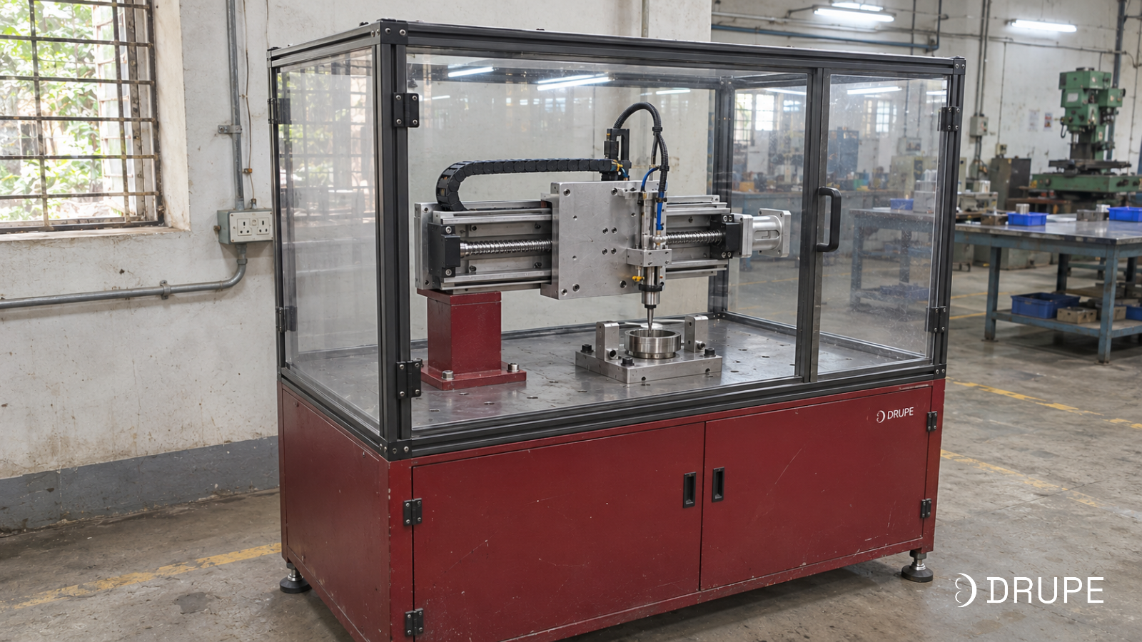
The same unit shows up inside very different machines. Duty cycle and environment change the specification far more than the industry label does.
1. Machine tool feed axes
Feed axes and spindle positioning, where preload set at assembly has to survive thermal cycling and vibration without a re-shim later. Ball screw throughout, with support units and locknuts specified as a single stack against the screw diameter. A relaxed locknut costs the most here, because the machine carries on running and parts carry on going out of tolerance long before anyone traces the cause.
2. Special purpose machines
One off machines built around a single part and a fixed cycle time, usually on a short programme. Availability competes with performance in this market. Every axis component has to come from one catalogue, sit on a shelf and arrive before the assembly bay frees up. A standard slide unit shipping this week beats a marginally better one carrying a ten week import lead time.
3. Robotics and automation
Transfer, loading and pick and place, where the axis travels far and fast then holds position once it stops. Belt slides do this work, combined into two and three axis gantries, with a rail clamp at each stop so the servo is not holding against load all shift. Reach measured in tens of metres rather than metres belongs in the gantry systems guide.
4. Packaging and pharma machinery
High cycle indexing axes running thousands of moves a shift. Life and lubrication dominate the specification here, not accuracy. Rated clamping cycles, continuous lubrication of rack and pinion drives by felt pinion and keyless hub mounting that needs no keyway cut are what set the interval between services.
5. Electronics and EV assembly
Short strokes placing small parts accurately, thousands of times a day, inside a tight envelope. Ball screw slides at plus or minus 0.02 mm, compact bodies, XY configurations and multi axis cells assembled from single axes. Envelope usually binds before load does.
6. Maintenance and replacement
Nobody plans for this one. A worn support unit or a slack locknut stops a running machine, and only two questions matter: which size is it, and does it ship today. Downtime is the cost, not the part, which is why a domestic supplier holding stock beats an imported brand with a better datasheet. Send a part number or a photograph and Drupe will identify it.
Moment load: why payload in kilograms is not enough?
Every buyer opens with payload in kilograms. Moment load is what usually decides whether the slide survives.
What it is. A payload bolted to a carriage almost never has its centre of gravity sitting over the rail. It sits out on an arm, a bracket, a gripper, a tool plate. That offset converts weight into a twisting force on the bearing blocks:
M = m * g * d
where m is the payload in kg, g is 9.81 m/s² and d is the distance from the rail face to the centre of gravity in metres. The answer is in newton metres.
A datasheet lists three of them separately:
- Pitch comes from an overhang along the direction of travel. The payload tries to tip the carriage forward.
- Yaw comes from an offset to one side, horizontally. The payload tries to twist the carriage about the vertical.
- Roll comes from a payload hanging off to the side. The payload tries to roll the carriage over. This is usually the harshest of the three.
Why kilograms alone mislead. One 20 kg payload produces wildly different moments depending on where its centre of gravity ends up. Measured against an illustrative 50 Nm permissible moment:
A 20 kg payload against a 50 Nm limit
| Payload | Centre of gravity from the rail face | Moment | Against a 50 Nm limit |
|---|---|---|---|
| 20 kg | 50 mm | 10 Nm | Well within |
| 20 kg | 100 mm | 20 Nm | Well within |
| 20 kg | 150 mm | 29 Nm | Within |
| 20 kg | 250 mm | 49 Nm | At the limit |
| 20 kg | 400 mm | 78 Nm | Over by half |
| 20 kg | 600 mm | 118 Nm | More than twice the limit |
The heaviest payload each overhang will take at 50 Nm
| Centre of gravity from the rail face | Heaviest payload at 50 Nm |
|---|---|
| 50 mm | about 100 kg (the block load rating governs first) |
| 100 mm | about 50 kg |
| 150 mm | about 34 kg |
| 250 mm | about 20 kg |
| 400 mm | about 12 kg |
| 600 mm | about 8 kg |
Orientation changes the answer again
This is why one slide carries different payloads in different mountings, and why a catalogue quoting a single payload figure tells you less than it appears to.
Horizontal,carriage on top. Weight presses straight down into the bearing blocks. Friendliest case, and the one catalogue payload figures usually describe.
Vertical. Weight now acts along the screw instead of down into the blocks, so thrust, screw buckling and the holding brake replace the rail as the limit. The centre of gravity offset still applies a constant pitch moment for as long as the axis is loaded. Drupe’s KK ball screw slide takes 40 kg horizontally and 10 kg vertically. Orientation alone produces that four to one difference, with nothing else changed.
Wall mounted, payload hanging off the side. Roll moment dominates, and this is normally the most restrictive of the three. Say so at enquiry stage if this is your mounting, because it can move the slide up two frame sizes.
Acceleration counts too
Static weight is only half the load. Accelerating the payload adds a horizontal force of F = m × a acting at that same centre of gravity, which feeds the same moment. Take 20 kg accelerating at 5 m/s² and you add 100 N at the centre of gravity. Out at a 250 mm overhang that is another 25 Nm stacked on the static 49 Nm, and an axis that looked borderline at rest is now comfortably past its limit.
So size against one combination: your heaviest payload, at its furthest centre of gravity, at your highest acceleration. That single case tells you more about fit than any payload line in a brochure.
These figures use the standard moment definition for a payload on a linear carriage. The 50 Nm limit is illustrative. Confirm the permissible pitch, yaw and roll moments for the specific slide with your supplier.
Why do ball screw slides stop at about one metre of stroke?
Look across any ball screw catalogue and general-purpose slides run out somewhere near a metre, after which belts take over. Nothing commercial is behind that. It is physics, and it explains the shape of the entire product range.
What happens. A ball screw is a long slender shaft spinning between two supports, and like any shaft it has a natural frequency at which it begins to whip. Approach that speed and the screw bows, vibrates, makes noise, grinds out its own nut and eventually fails. Permissible speed falls with the square of unsupported length, so the problem arrives all at once rather than creeping up on you.
Industry works from this approximation:
N_{cr} = f \times \frac{d_r}{L^2} \times 10^7where N is in rpm, d is the screw root diameter in mm and L is the unsupported length in mm. The factor f depends on how the ends are held: roughly 3.4 for fixed and free, 9.7 for supported at both ends, 15.1 for fixed and supported, 21.9 for fixed at both ends. A safety factor of 0.8 is then applied.
What that looks like in practice. Take a 16 mm screw with a 5 mm lead, fixed at the drive end and supported at the far end:
| Distance between supports | Safe screw speed | Linear speed at 5 mm lead |
|---|---|---|
| 500 mm | about 6,400 rpm | about 530 mm/s |
| 750 mm | about 2,800 rpm | about 235 mm/s |
| 1,000 mm | about 1,600 rpm | about 130 mm/s |
| 1,500 mm | about 710 rpm | about 60 mm/s |
| 2,000 mm | about 400 rpm | about 33 mm/s |
| 3,000 mm | about 180 rpm | about 15 mm/s |
Double the length and three quarters of the speed disappears. Out at three metres that same screw crawls along at roughly 15 mm/s, while a belt slide of equal stroke runs up to 3,000 mm/s unloaded. Two hundred times the speed is why these technologies stop competing above about 1.5 metres.
What you can do about it. Three levers, most useful first:
- Use a bigger screw. Speed scales directly with root diameter. Going from 16 mm to 25 mm buys roughly 50 per cent more speed at the same length, at the cost of inertia and money.
- Use a longer lead. A 10 mm lead doubles the linear speed at the same rpm. You lose thrust and resolution in exchange, so this works for transfer moves and not for pressing.
- Drive the nut instead of the screw. On a rotating nut design the screw does not turn, so critical speed stops applying. It costs more and is uncommon on standard slides.
A second limit sits at the other end of the range. Screws in compression buckle, and permissible buckling load also falls with the square of length. A long vertical ball screw pushing a load downward is the case where both limits close in together.
The table is calculated from the stated assumptions, not taken from a catalogue. Screw diameter, lead, end fixity and the actual support spacing change every figure. Confirm against the specific slide before you design around it.
Linear slide life, lubrication and failure modes
Rated life
Rolling element bearings carry an L10 rating: the travel distance at which 90 per cent of a population of identical bearings would still be running. Statistical, in other words, and not a guarantee about your particular slide.
Linear guides quote it in kilometres of travel, following a cube relationship with load:
L = \left(\frac{C}{P}\right)^{3} \times 50where C is the dynamic load rating of the block, P is the actual load on it and L comes out in kilometres. The cube is the part worth internalising. Halving the load gives you eight times the life. Doubling it costs you seven eighths. A slide running at half its rating will outlast one running at its rating by a factor most people badly underestimate.
Turning that into a service interval means working out daily travel: stroke, times moves per cycle, times cycles per hour, times hours per day. An axis making a 400 mm move 300 times an hour across 16 hours covers about 1,900 metres a day, or roughly 700 km a year. Set against a rated life of 20,000 km, comfortable. Set against 2,000 km, a yearly rebuild.
Lubrication
More slides die of lubrication than of load. Settle three things at design stage rather than after commissioning.
Method. Manual grease nipple, grease cartridge or a central lubrication line. Anything on a high duty cycle belongs on a central line, because a point needing attention every fortnight will not get it.
Access. Grease points you can reach on the bench get buried once the guards go on. Check reach with the machine assembled, not with the slide sitting on a table.
Specification. Temperature, speed and environment all have to match the grease. Food contact needs food grade. High temperature needs high temperature. Mixing incompatible greases at the first service is a real failure and a common one.
On rack and pinion drives, a felt pinion running in mesh lays a continuous film across the teeth and deletes the manual greasing step entirely, which is the whole reason it exists as a standard component.
The five ways slides fail
Symptom | Likely cause | What to check first |
|---|---|---|
Repeatability drifts over months, position creeps | Preload relaxed at the fixed end, axial play has appeared | The locknut. This is the most common single cause and the cheapest to fix. |
Notchy or rough travel, audible rumble | Contamination in the raceway, or lubrication starvation | Wipers and seals, then grease interval. Then look for what is getting in. |
Axis runs hot, motor current higher than it was | Over preload, misalignment of the mounting face, or a bearing beginning to seize | Mounting flatness with a straightedge, then the preload class on the spec |
Position error grows with speed but not at crawl | Drive train, not guides: belt stretch, coupling slip or resonance near critical speed | Belt tension, coupling grub screws, then screw speed against the critical speed limit |
Sudden failure after a long quiet period | Cable or energy chain, not mechanics | Conductors at the chain’s bend radius. Cables fatigue and break long before bearings wear out. |
A pattern sits underneath that table. Slow drift is almost always preload. A rough feel is almost always contamination. A sudden stop is almost always a cable. Check in that order and most problems surface before anything gets dismantled.
Should you buy a linear slide or build the axis yourself?
Every machine builder has built an axis out of parts, and every one of them has a story about the week it ate. Worth doing the comparison properly, because unit price is the line everyone compares and the smallest number in the total.
Built from parts. Rail, two or four blocks, ball screw, nut housing, fixed support unit, free support unit, locknut, coupling, motor mount, plus a machined base and a machined carriage plate. Ten part numbers across four or five suppliers, each with its own lead time and its own minimum order.
Bought as a slide unit. One part number, one lead time, one datasheet and one place to send the problem if it underperforms.
Line | Built up axis | Slide unit |
|---|---|---|
Part numbers to source | 8 to 12 | 1 |
Suppliers and lead times to track | 4 to 6 | 1 |
Design and detailing | 8 to 12 engineering hours | About 1 hour to select |
Machining | Base and carriage plate, ground flat and parallel, usually an outside job | None |
Assembly and alignment | 4 to 8 hours on the bench, with a dial gauge | Bolt down and shim |
Accuracy you can quote | Whatever you measure after it is built | Published before you buy |
Who owns a problem | You | The supplier |
Replacement in year three | Rebuild the stack | One part number |
Those hour figures are typical rather than measured, so substitute your own. The conclusion holds regardless: engineering, machining and alignment time normally exceeds the price gap between the two routes, and it gets paid in the scarcest currency a machine builder has, which is senior engineering hours in the middle of a build.
When building it yourself is genuinely right
Three cases, all real.
- The envelope is unusual. The axis has to wrap around existing structure, fit a cavity no catalogue body fits or carry mounting features no standard carriage has.
- The load is outside the range. Heavy, long or both. Above a metre and a half of stroke with real load, you are designing a linear track and should read it as that problem.
- You are building the same machine fifty times. At volume, the engineering is amortised and the part cost gap becomes the whole argument. Below about ten units it almost never pays.
What to compare instead of unit price
For machine builders the useful metric is cost per commissioned axis, not cost per part. Add up the parts, the engineering hours, the machining, the bench time, the commissioning time and the cost of stripping and re-aligning one axis after the customer has seen it. Then compare. A slide unit priced 30 per cent above the parts list still wins most of the time, and it wins hardest on the build that is already running late.
How to specify a linear slide: a 13 point checklist
Hand a supplier everything below and the slide that comes back will fit your machine. Hand them stroke and payload only and you will get the catalogue unit nearest to that pair, followed by a long exchange of emails once it reaches your bench.
Item | Why it matters |
|---|---|
Motion |
|
1. Stroke required, plus over travel and home offset | Sets the body length. Usable stroke is always less than body length. |
2. Mounting orientation: horizontal, vertical, wall | Changes permissible payload by a factor of four or more on the same slide. |
3. Maximum speed and acceleration | Sets the drive choice, the motor and whether critical speed binds. |
4. Repeatability needed at the payload | Decides ball screw against belt, and the screw grade within that. |
Load |
|
5. Payload mass | Sets the frame size. The starting number, not the finishing one. |
6. Centre of gravity distance in all three directions | Sets the moment load, which is usually the real limit. |
7. Process force: pushing, pressing, clamping, cutting | Sets the thrust required and often rules belt out entirely. |
Duty and environment |
|
8. Cycles per hour and hours per day | Sets the rated life calculation and the lubrication interval. |
9. Dust, swarf, coolant, spatter, washdown, temperature | Decides covers, seal class and whether a belt is viable at all. |
10. Holding at a stop, and behaviour on power loss | Decides brake, rail clamp or counterbalance. Not optional vertically. |
Integration |
|
11. Motor and drive brand already on your machine | Decides mount, coupling and whether the inertia ratio works. |
12. Controller, feedback and homing method | Decides the sensor package and the wiring to allow for. |
13. Mounting interface on your frame and payload | Decides whether an adapter plate is needed, which raises the moment. |
Factors that often get missed
Usable stroke is not body length. End caps, carriage length, over travel and the home position all take a share. Specify the distance the payload has to travel and let the supplier work backwards to a body length.
The adapter plate you have not drawn yet. Teams size a slide against the payload, discover the mounting pattern does not line up and bolt on a 40 mm plate. That plate pushes the centre of gravity 40 mm further out and adds moment to an axis already at its limit. Settle the interface before sizing the slide.
Inertia ratio. A light carriage driven by a heavy motor through a direct coupling tunes as badly as the reverse. Agree the ratio with whoever sizes the motor before the slide is ordered.
Cable management. Cables travel with the carriage. An energy chain needs its own bend radius, its own mounting and its own space inside the envelope. Underrated chains fail more often than worn bearings do.
Lubrication access after assembly. Covered above, and worth repeating because it is the one people only discover during the first service.
Alignment is half the axis. A slide unit arrives aligned internally. It cannot fix a mounting surface that is not flat. Mounting a precision slide onto a frame that is out by 0.5 mm over its length pre-loads the rails against each other, raises friction, heats the blocks and shortens life, and none of that shows up on a dial gauge at standstill. Specify the flatness of the mounting face and shim to it. This is the most common reason a slide fails to meet its published figure in service.
Drupe linear slide specifications
Drupe manufactures linear slides and the standard components around them at MIDC Taloja, holding standard sizes in stock and dispatching from Navi Mumbai.
| Ball screw slide (KK) | Belt driven slide (LFR 10) | |
|---|---|---|
| Stroke | 50 to 1,050 mm | 100 to 3,900 mm |
| Repeatability | plus or minus 0.02 mm | plus or minus 0.05 mm |
| Speed | Suited to positioning duty | Up to 3,000 mm/s unloaded |
| Thrust | 376 N | Not a thrust application |
| Payload, horizontal | Up to 40 kg | Up to 30 kg |
| Payload, vertical | Up to 10 kg | Specify with brake |
| Typical use | Positioning, measurement, assembly, pressing | Transfer, loading, gantry axes |
Six series run across the range: KK, LFR, LMCB, LMX, LMG and LMW. LMCB is the compact option and comes in XY configurations, while single axes combine into two and three axis gantries holding plus or minus 0.05 to plus or minus 0.1 mm repeatability in medium and heavy duty. Span, payload and drive type all move that gantry figure, so it is confirmed against your configuration at quotation.
| Component | Range | What it does |
|---|---|---|
| Precision locknuts KMR, KMK, KSF, KAM | M8 to M200 | Lock on the thread itself. No thrust washer, no keyway. |
| Support units BK, BF, FK, FF | Shafts 10 to 40 mm | Fixed and supported housings for ball screw ends. |
| Rail clamps HZ | Rail 15 to 65 mm | Hold the carriage at a stop so the drive is not fighting the load. |
| Felt pinions | Run in mesh with a rack or gear | Lay a continuous lubricant film, replacing manual greasing. |
| Power locks | Keyless locking assemblies | Clamp a hub to a shaft by friction. Zero backlash, no keyway. |
Choosing between the four locknut series. KMR runs M8 to M56 and locks with a grub screw. KMK runs M16 to M200 and is the widest range. KSF runs M14 to M110 and locks at three points on brass threads to 35 Nm, which makes it the safer choice under vibration. KAM runs M12 to M150 and has opposed flats below M15 so a general wrench fits.
The rest of the detail. BK and BF support units bolt down through the base, FK and FF mount to a face, with the same internal arrangement, so the choice follows how your frame is built. HZ rail clamps hold 1,200 to 2,000 N, are rated to 25,000 clamping cycles, run from minus 10 to plus 70 °C and are set by lever at 4 to 22 Nm. Power locks clamp as the screws draw two tapered rings together, so the hub sits anywhere on the shaft and comes off without damage.
Manufacture
Locknuts are turned from EN19 bar on high precision machines and hardened to HRC 28 to 32. Thread precision is ISO 4H and run out is held to 0.005 mm, measured rather than assumed, which is what allows the figure onto an inspection report. The same specification runs across all four locknut series, and every component is inspected before despatch.
Each limit above stands on its own and they are not all reachable on one axis simultaneously. Longest strokes do not arrive with highest payloads. Send your stroke, payload, centre of gravity and duty cycle and Drupe will confirm the selection against your actual axis.
Where Drupe's linear slide range fits
Drupe builds linear slides and standard components inside a wider motion range, designed and manufactured by the same team that builds Drupe’s welding and cutting automation.
Linear slides. Ball screw and belt driven slide units from 50 to 3,900 mm of stroke, specified together with their support units and locknuts as a single stack.
Standard components. Precision locknuts, support units, rail clamps, felt pinions and power locks, held in standard sizes so a replacement is a despatch rather than an import lead time on a part worth a few hundred rupees.
Multi axis systems. XY and three axis gantries built from those same slides, for transfer, loading and pick and place.
Linear tracks and gantries. For stroke and load beyond what a slide handles: robot 7th axes, cutting gantries and material shuttles on a welded and machined steel base.
Special purpose machines. Complete machines where no standard envelope fits, built on the same in-house mechanics and controls.
Why that range matters when you are choosing a slide
Most linear slide suppliers sell components and leave axis design to you. Most machine builders buy components and meet the axis problem at assembly. Drupe does both, so the conversation can start at the axis instead of the part number. Describe something that actually needs a track rather than a slide, or a split into two axes rather than one compromise, and you will hear that at enquiry stage rather than after the first unit lands on your bench.
Drupe has designed and built industrial automation since 1992, with machines running at L&T, Godrej, JCB, BARC, Mahindra and Indian Railways, and installations across 16 countries.
Talk to Drupe about your axis
Send stroke, payload, the distance from the carriage face to the centre of gravity, mounting orientation, speed and cycles per hour. Add the environment and the motor brand you already use. Our team will confirm slide size, drive type and the support units and locknuts that go with them, or tell you plainly if your axis needs something other than a slide.
Request a selection or write to sales@drupeengg.com. If you are replacing a worn part on a running machine, send the part number or a photograph and we will identify it.
Frequently asked questions
A linear slide is a pre assembled linear axis made up of a rigid base, precision guide rails, a moving carriage and a drive, supplied as one unit with a published accuracy. You bolt it to your machine and connect a motor instead of building the axis yourself from rails, screws and plates.
A linear rail is a component: hardened steel with bearing blocks, sold by the metre and used inside machines. A linear slide is a finished axis built around those rails, with its own body, drive, carriage and a stated repeatability figure.
Yes. Linear slider, linear slide, linear module and single axis robot all describe the same family of product in most catalogues. The question worth asking is not what it is called but what the specification leads with. Accuracy and repeatability means a slide. Thrust and stroke means an actuator.
Ball screw buys accuracy and thrust over short stroke. Belt buys length and speed. Drupe’s KK ball screw slide holds plus or minus 0.02 mm from 50 to 1,050 mm with 376 N of thrust, while the LFR 10 belt slide runs 100 to 3,900 mm at up to 3,000 mm/s unloaded at plus or minus 0.05 mm. Few applications genuinely need both in one axis, and those that do are better served by two axes than one compromise.
That depends on orientation and on where the centre of gravity sits. The KK ball screw slide takes up to 40 kg horizontally and 10 kg vertically. The LFR 10 belt slide takes up to 30 kg horizontally. Payload, stroke and mounting orientation decide the selection together, which is why all three are needed at enquiry stage.
Critical speed. A spinning screw whips above a certain rpm, and permissible speed falls with the square of unsupported length. Double the length and roughly three quarters of the speed goes, so past about 1.5 metres a ball screw becomes impractically slow and belt drive takes over.
Repeatability of plus or minus 0.05 to plus or minus 0.1 mm across one, two and three axis gantries in medium and heavy duty. Span, payload and drive type all move that figure, so it is confirmed against your configuration at quotation.
Whenever the carriage holds position at a stop and you would rather the drive was not fighting the load continuously. HZ manual clamping units suit rails from 15 to 65 mm, hold 1,200 to 2,000 N, are rated to 25,000 clamping cycles and run from minus 10 to plus 70 °C.
Yes, with a motor brake. Neither a ball screw nor a belt self locks, so a vertical axis back drives under gravity once power is removed. Permissible payload also drops sharply in the vertical orientation, typically by a factor of three or four on the same slide.
Stroke, drive type, accuracy class, payload and whether motor, brake and clamps are included all move the price. Send stroke, payload, orientation and duty cycle for a quotation built on your axis rather than on a catalogue line.
