

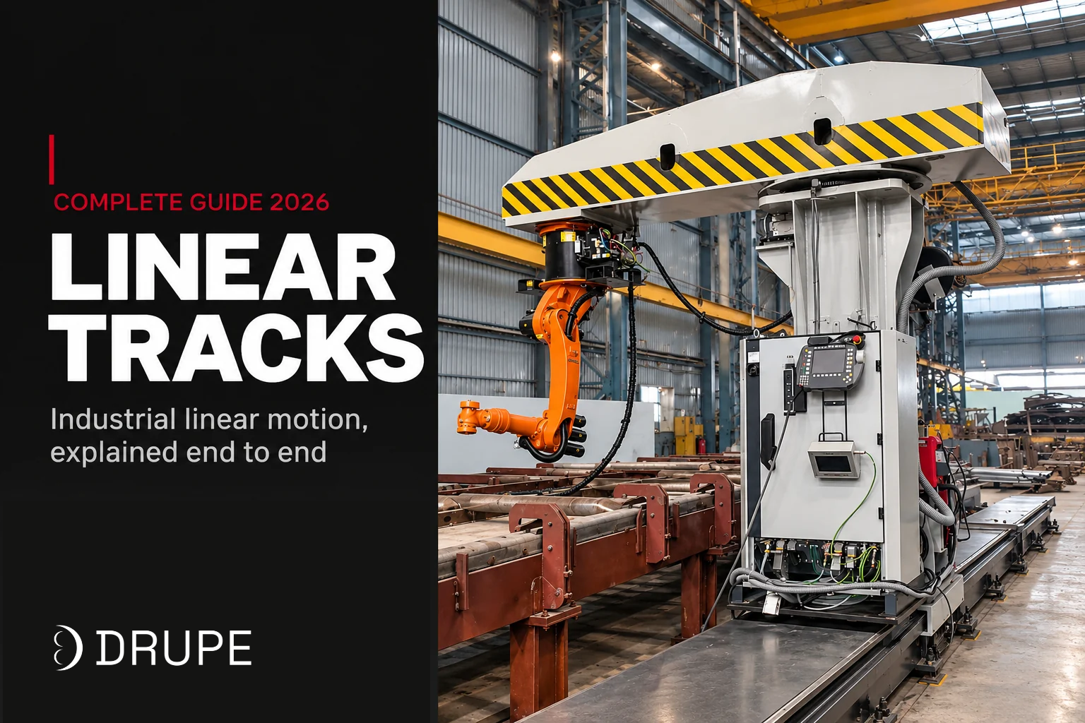
-
By Zaid Khan
-
October 28, 2026
- 0 Comment
Linear Tracks: Industrial Linear Motion Systems Explained
Open almost any production machine and the first axis you see is linear. A plasma head traversing a cutting table. A welding torch gliding along a boom. A robot sliding past three fixtures. A gantry shuttling a pallet across a packing bay. Behind every one of those motions is a linear track doing a specific job: moving one thing in a straight line, accurately, over a defined distance, as many times as the process demands.
The term is used loosely. Some suppliers call a 300 mm bearing block on a rail a linear track. Others reserve the term for a 30 metre robot runway with its own servo and controller. Both are correct in their own way, and that is exactly why buyers get confused when they start comparing products.
This guide fixes the vocabulary first. It then walks through what a linear track actually is, the mechanisms that drive it, how industry puts them to work and the handful of numbers that decide which track is right for your machine. If you are shortlisting a 7th axis for a robot, the companion piece Robot Linear Tracks (7th Axis): How They Work and When You Need One goes deeper on that specific case.
The linear motion family: table to save your time
Most of the confusion in buying linear motion comes from treating the whole family as one product. Each term below means a different thing, and each has its own suppliers, price range and typical use.
| Term | What it is | Where you'll find it |
|---|---|---|
| Linear rail (linear guide) | A precision steel rail with recirculating ball or roller bearing blocks running on it. A component. | Inside almost every CNC axis, servo stage and motion module. |
| Linear bearing block | The carriage that runs on a linear rail. Chosen by load rating and preload class. | Standalone or mounted on a plate to make a slide. |
| Linear slide | A short-stroke precision assembly: linear rails, bearings, a moving stage, usually a ballscrew drive. | Semiconductor and measurement equipment, laboratory benches, pick-and-place. |
| Linear actuator | A motorised push-pull device: electric cylinder, ballscrew actuator or belt-driven unit. | Clamping, lifting, nozzle adjustment, press feed. |
| Linear track (industrial linear track) | A complete heavy-duty motion system: welded steel base, precision guides, servo drive, controller interface and safety. | Robot 7th axes, cutting-machine gantries, welding manipulators, material shuttles. |
| 7th axis | A linear track that is coordinated with the robot it carries, as the seventh axis of the robot's controller. | Welding and cutting cells where the arm must work while the base is moving. |
| Linear motor stage | A direct-drive linear motion stage with no ballscrew or belt, driven by a flat linear motor. | High-speed semiconductor, inspection, flat-panel manufacturing. |
| Gantry (XY, XYZ) | Two or three linear tracks arranged as perpendicular axes to give a rectangular work envelope. | Plate cutting machines, large-format printers, overhead material handling, palletising. |
Two things are worth noting. First, a linear rail is a part; a linear track is a product. The precision rails you can order by the metre from component suppliers sit inside almost every track built on the market. The engineering that turns those rails into a reliable, long-travel motion machine is where track manufacturers like Drupe come in. Second, the words “actuator” and “slide” are often used interchangeably in catalogues. The distinction that matters is the stroke and the load: short and precise is a slide, longer and higher-force is an actuator.
If you remember one line, remember this: a linear rail is a bearing; a linear track is a machine.
What a linear track is? (in detail)
A linear track is a complete, self-contained motion machine. You bolt it to the floor or a frame, connect its servo to a controller, and it will move a payload in a straight line to any taught or programmed position, every cycle, within a defined tolerance.
Three things separate a linear track from a longer linear rail with a motor bolted onto it:
- A rigid base that holds its own geometry. A welded and machined steel beam that stays straight and flat over the full length, independent of how level the floor underneath happens to be. Shimming at installation fixes the rest.
- A drive system sized for the load and the duty cycle. Not just a motor that will move the carriage, but a servo, gearbox and drive mechanism engineered to accelerate the full payload safely tens of thousands of times.
- Safety and controls as part of the product. Limit switches, over-travel bumpers, safety-rated feedback and the electrical interface to a controller or a robot are specified and tested, not left to the integrator.
This is why a 10 metre linear track costs a lot more than 10 metres of linear rail plus a motor. You are paying for the engineering that keeps the geometry correct over long travel, the drive sizing that keeps it reliable under load and the integration that lets a robot or a CNC treat it as a trusted axis.
The trade-off runs the other way too. A linear slide inside a measurement machine does not need any of this. It needs a short, very straight rail, a precision ballscrew and a quiet motor. Buying a heavy track for a job a slide can do is just as wrong as buying a slide for a job a track needs.
Anatomy of a linear track
Strip the covers off any industrial linear track and you will find the same seven building blocks, scaled to the application.
Base frame. A welded steel beam, machined flat and straight after welding so the guides sit true along the full length. On tracks longer than a truck bed, the frame comes in bolted modules that are keyed and dowelled where they join. The flatness and straightness of this beam set the ceiling for every other precision figure the track can hit.
Linear guides. Two parallel precision rails bolted to the base, with bearing blocks that run on them. Recirculating ball guides are the default for medium loads; roller guides are chosen for very heavy loads and high rigidity. The brand, class and load rating of the guides on a track’s datasheet tells you more about its real quality than most other lines.
Drive mechanism. The system that converts rotary motion into linear motion along the track. Rack and pinion, ballscrew, toothed belt or linear motor. The next section walks through when each is right.
Carriage. The steel plate the payload (robot, cutting head, part, fixture) bolts to. It carries the drive output (pinion, nut or belt coupling), the bearing blocks, and the end of the cable chain. On robot tracks, the robot’s own base pattern is machined into the carriage.
Servo motor and gearbox. A servo motor sized to the inertia of the payload, paired with a planetary gearbox on rack-and-pinion tracks or a direct coupling on ballscrews. A good drive gives you consistent position and velocity under load; a cheap one gives you jerky starts, lagging stops and shortened life.
Cable and energy chain. An articulating chain that carries power, encoder, signal and process cables (and often air and water hoses) along with the carriage. Underrated cable chains are the single most common source of failure on industrial tracks: cables fatigue, break and short long before the bearings wear.
Controls and safety. Hardware limit switches at both ends of travel, over-travel bumpers, a safety-rated encoder (or dual channel feedback) and the electrical interface that lets a controller or a robot control the axis. On cells with people nearby, add safety-rated light curtains, laser scanners and emergency-stop circuits.
Any spec sheet that only talks about speed and travel without naming the guides, drive and cable chain is hiding the parts that decide reliability.
Drive mechanisms compared
The drive is the single biggest decision that shapes a linear track’s travel, speed, accuracy and cost. There are four options worth knowing, each with a clear sweet spot.
| Drive | How it works | Positional accuracy | Travel it scales to | Speed | Best for | Trade-offs |
|---|---|---|---|---|---|---|
| Ballscrew | A precision screw turns; a nut on the carriage translates rotation into linear motion. | High (±0.01 mm class on good screws) | Short to medium (up to about 3 to 4 m) | Low to medium | Precision slides, machine axes, measurement equipment | Screw whip and critical speed limit how long and how fast you can run; expensive at length. |
| Rack and pinion | A pinion gear on the carriage rolls along a toothed rack bolted along the base. | Medium to high (±0.05 to ±0.1 mm on well-tuned systems) | Short to very long (over 30 m, bolted modules) | Medium to high | Robot linear tracks, long material shuttles, large plate cutting gantries | Needs lubrication; backlash has to be controlled with preload or dual pinions. |
| Toothed belt | A steel-reinforced belt is driven by a servo pulley at one end. | Medium | Short to long | High (can exceed 5 m/s) | Light payloads, high-speed handling, Cartesian pick-and-place | Belt stretch and wear; not ideal for heavy, slow, precise work. |
| Linear motor | A direct-drive linear motor: no screw, belt or rack. The motor coils move the carriage along a magnetic track. | Very high (sub-micron possible) | Short to medium | Very high | Semiconductor, flat-panel, inspection, high-speed assembly | Expensive; sensitive to contamination; cannot handle heavy loads cost-effectively. |
Which linear track mechanism is best for you?
For industrial automation in heavy fabrication, almost every linear track you will specify is rack and pinion. It is the only drive that scales cleanly to the lengths and loads a welding or cutting cell actually needs.
Types of linear tracks by application
The same four core components (base, guides, drive, carriage) show up in very different industrial jobs. The use case decides the size, drive and controller more than any catalogue family does.
1. Linear tracks as machine axes
Almost every CNC cutting machine, welding manipulator and automated inspection system is built on linear tracks. The X and Y axes of a plasma or oxyfuel plate cutting gantry, the vertical travel of a column and boom welding manipulator, the drag chain of a pipe cutting machine, all of them are linear tracks under the covers.
For these, the track is designed around the process, not the catalogue. A cutting gantry needs long X travel, consistent speed under load, protection from slag and spatter, and a drive that can hold speed through the fastest sweeping cuts. A welding manipulator needs smoother motion at low speeds and tight resistance to vibration.
2. Linear tracks for material handling
On packing lines, press shops, foundry transfer systems and inter-process shuttles, a linear track is often the simplest way to move heavy items from one point to another. The payload sits on the carriage directly, there is no robot involved, and the controller only has to send the carriage to taught positions.
These tracks are brutal environments: heat, dust, oil, repeated collisions. Robustness and cable chain protection matter more than precision.
3. Robot 7th axis
A robot linear track, or 7th axis, carries a six-axis industrial robot. The robot’s controller treats the track as its seventh coordinated axis, which lets the arm continue welding or cutting while the base is moving. Typical use cases: long welding seams, multi-station welding or cutting cells, loading large or heavy parts, tending multiple CNC machines in sequence.
For the full treatment of this case, see Robot Linear Tracks (7th Axis): How They Work and When You Need One.
4. Gantry systems
A gantry is a set of linear tracks arranged as perpendicular axes. Two tracks for an XY gantry (used on most plate cutting machines), three for an XYZ gantry (used on large pick-and-place and palletising systems and some painting robots). The payload hangs from the moving crossbeam of the Y axis.
Gantries are chosen when the work envelope is large and rectangular, when overhead work is needed, or when floor space does not allow a floor-mounted track long enough. A gantry costs more and is more complex to install than a single floor-mounted track.
5. Measurement and inspection
Coordinate measuring machines (CMMs), vision inspection stations, surface scanning stages and leak testing lines all run on short, very precise linear tracks or slides. Repeatability and straightness dominate the specification; speed and payload are modest.
These are the only cases where ballscrews or linear motors routinely beat rack and pinion.
Precision classes: what the numbers mean and what they cost?
hree numbers describe the precision of any linear track. They are often confused in buying conversations because they sound similar and tell you different things.
Positioning accuracy. How closely the carriage reaches an absolute coordinate when commanded. This number tracks the straightness of the base, the pitch error of the drive and the backlash in the gear train.
Repeatability. How closely the carriage returns to the same taught position every time, measured over many cycles. Repeatability is almost always better than absolute accuracy because it does not care about the overall straightness of the beam, only about returning to the same spot.
Straightness and parallelism. How much the carriage deviates from a perfect straight line as it travels, both horizontally and vertically. For a cutting or welding path, this matters more than the absolute coordinate.
Typical ranges by application
Three numbers describe the precision of any linear track. They are often confused in buying conversations because they sound similar and tell you different things.
Positioning accuracy. How closely the carriage reaches an absolute coordinate when commanded. This number tracks the straightness of the base, the pitch error of the drive and the backlash in the gear train.
Repeatability. How closely the carriage returns to the same taught position every time, measured over many cycles. Repeatability is almost always better than absolute accuracy because it does not care about the overall straightness of the beam, only about returning to the same spot.
Straightness and parallelism. How much the carriage deviates from a perfect straight line as it travels, both horizontally and vertically. For a cutting or welding path, this matters more than the absolute coordinate.
| Application | Positioning accuracy | Repeatability | What drives it |
|---|---|---|---|
| Robot 7th axis for welding and cutting | ±0.1 to ±0.3 mm | ±0.05 to ±0.1 mm | Rack-and-pinion track; robot's own path accuracy dominates downstream. |
| CNC cutting machine axes | ±0.1 to ±0.2 mm | ±0.05 mm or better | Precision rack-and-pinion with electronic preload. |
| Precision linear slide (short stroke) | ±0.01 mm class | ±0.005 mm | Ballscrew C3 or C5, high-grade guides. |
| CMM / inspection stage | sub-±0.005 mm | sub-±0.001 mm | Linear motor, air bearings or high-grade ballscrew in a controlled environment. |
| Material handling shuttle | ±0.5 to ±1 mm | ±0.1 to ±0.2 mm | Rack and pinion with standard preload. |
Why over-specifying is a trap?
Asking for CMM-grade accuracy on a 10 metre welding track adds cost without adding value. Welding travel speeds and arc stability dominate the final seam quality, not whether the carriage reaches its coordinate within 10 microns or 100.
The quiet rule in heavy fabrication: repeatability needs to be a factor of 10 better than the process tolerance you care about. For a 1 mm fit-up tolerance on a weld joint, ±0.1 mm repeatability is more than enough. Pay for more only if the process actually demands it.
How to specify a linear track?
If you give a supplier the eight items below, you will get a quote that fits your job. If you give them “length” and “payload” and nothing else, you will get a quote for the catalogue product closest to that pair, and then a long back-and-forth to make it work in your cell.
Sizing checklist
| Item | Why it matters |
|---|---|
| Payload (kg, including robot, end effector and part if any) | Sets the carriage, guides and drive sizing. |
| Travel (full length and clear usable length) | Sets the frame and whether modular joints are needed. |
| Maximum speed and acceleration | Sets the servo, gearbox and gear ratio. |
| Duty cycle (moves per hour or per shift) | Sets the service life sizing of the drive, guides and cable chain. |
| Repeatability required at the carriage | Decides the drive family, feedback and backlash control. |
| Mounting (floor, inverted, gantry) | Changes the structural steel around the track and the cable routing. |
| Environment (welding spatter, cutting slag, oil, dust, washdown) | Decides covers, chain IP rating and seal classes. |
| Controller or robot interface | Decides whether to ship a tested 7th axis package or a standalone track. |
Environmental factors that often get missed
Welding spatter will eat anything it can reach. Linear tracks in welding cells need either covers over the rails and the rack, or spatter-resistant guards and cable chains that can be hosed or brushed clean.
Cutting slag is hotter and heavier. On plate-cutting gantries, keep the carriage and cable chain clear of the kerf line, slope guards so slag falls off and use a slag tray under the chain run.
Oil and coolant from CNC machine tending cells creep into cable chains and bearing blocks. Use IP-rated chains and seals, and specify a slow bearing degradation under contamination rather than the pristine catalogue value.
Mounting is half the installation
A 15 metre track is only as straight as the pad it sits on. Grouting the base plate at every anchor, shimming to the supplier’s spec and checking the straightness end-to-end with a laser are not optional. A poorly grouted installation is the single most common reason a long track fails to meet its spec in service.
Where Drupe's linear motion range fits
Drupe builds across the linear motion range, from short precision slides to heavy robot runways, with the same engineering team that builds Drupe’s cutting and welding automation. That matters because almost every linear motion requirement in heavy fabrication sits inside a process, not outside it, and the people sizing the track understand that process.
LFR linear slides and LMCB mounting components. Short-stroke precision slides for fixtures, tooling, measurement stations and sub-assemblies. The LMCB mounting components make it quick to integrate slides into existing machines or custom special-purpose machines (SPMs).
Linear Tracks. Heavy-duty industrial linear tracks for robot 7th axes, welding and cutting cells and material shuttles. Rack-and-pinion driven, built on a welded and machined steel base, with cable chains and covers specified for the shop environment they run in. Pre-integrated external-axis packages are available for ABB, KUKA, FANUC and Yaskawa robots.
Gantries. XY and XYZ gantry systems for large rectangular work envelopes: plate cutting machines, overhead material handling, inverted robots and large pick-and-place systems.
Robotic Cells. Complete welding and cutting cells with the robot, 7th axis, fixtures, safety and controls designed as one system. The track is specified for the process it will run.
Welding and cutting automation. Column and boom manipulators, plate and pipe cutting machines, pipe bevel cutters and welding rotators, all of which sit on linear tracks built in-house.
Why that end-to-end capability matters?
Most linear motion suppliers sell catalogue tracks. Most process automation suppliers buy linear motion from someone else and build around it. Drupe does both, which means the track specification does not get decoupled from the process it serves. A 10 metre welding track leaves the facility with its servo tuning, dynamic model and cable chain already matched to the welding robot it will carry and the parts it will weld.
Drupe has designed and built industrial automation since 1992. If you have a process in mind and are not sure whether a slide, a track, a gantry or a full robotic cell is the right answer, that conversation is where to start.
Talk to Drupe about your linear motion project
Tell us the process (welding, cutting, handling, inspection), the payload, the travel and the environment. Our team will size the right linear motion solution, whether that is a precision slide, a heavy-duty linear track, a gantry or a complete robotic cell.
Request a consultation or write to sales@drupeengg.com.
Frequently asked questions
A linear track is an industrial motion system that moves a payload in a straight line along a fixed path. It has a rigid base, two precision guide rails, a motor-driven carriage and a controller interface. Linear tracks range from short, high-precision stages used inside machines to 30 metre robot runways that carry industrial robots across a shop floor.
A linear rail is a precision component: a steel rail with bearing blocks that run along it, bought by the metre and used inside machines. A linear track is a complete machine built around linear rails, with its own frame, drive, servo motor, controller interface and safety system.
Four drive mechanisms are common: ballscrew (short, precise), rack and pinion (long, strong), toothed belt (fast, light) and linear motor (sub-micron accuracy in clean environments). Industrial robot tracks and long welding or cutting axes are almost always rack and pinion.
Precision depends on the drive and the application. A robot 7th axis typically holds ±0.05 to ±0.1 mm repeatability, a cutting-machine axis around ±0.05 mm, a short precision slide ±0.005 mm, and a CMM stage below ±0.001 mm. The right class is the one your process actually needs, not the tightest one on the market.
Rack-and-pinion tracks are built in bolted modules and routinely reach 20 to 30 metres or more. Ballscrew tracks are limited to about 3 to 4 metres by screw whip. Belt-driven tracks sit between the two.
Five main uses: as the axes of CNC cutting and welding machines, as material handling shuttles, as the 7th axis of industrial robots, as XY or XYZ gantries, and as the stages of measurement and inspection equipment.
Start with payload, travel and the environment. Add required speed, acceleration, duty cycle and repeatability. Decide on mounting (floor, inverted or gantry) and the controller or robot it will connect to. Those eight items drive the whole specification.