

- By Sayeed Mokashi
- November 4, 2026
- 0 Comment
Gantry Systems: Industrial Gantries Explained
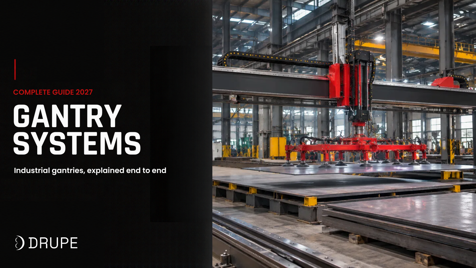
Walk into a plate shop and look up. A bridge spans the cutting bed, carrying a plasma torch across a 3 metre wide plate. In the next bay, a robot hangs upside down from a beam, welding a box girder that is too long to reach from the floor. At the end of the line, a gripper drops from an overhead frame, picks a finished part and sets it on a pallet. Three very different jobs, one shared idea: a gantry.
Like “linear track”, the word is stretched in every direction. A desktop 3D printer has a gantry. So does a 40 tonne container crane at a port. A cutting machine supplier and a palletising integrator will both quote you a “gantry” and mean completely different machines. That is why gantry comparisons go wrong so often: buyers line up quotes that are not describing the same thing.
This guide fixes the vocabulary first. It then explains what an industrial gantry actually is, how it is built, the configurations and drives that matter, where industry uses it and the handful of numbers that decide whether a gantry is right for your job. If you have not read it yet, our Linear Tracks guide covers the single axis that every gantry is built from.
A bevel is the angled edge cut on a pipe end so two pipes can be butt welded with full penetration. Put two bevelled ends together and they form a V-shaped groove. The welder fills that groove from the root at the inside of the pipe to the cap on the outside.
Three dimensions decide whether that weld goes smoothly:
- Bevel angle: the slope of the cut face. Too steep and the welder cannot reach the root. Too shallow and you waste filler metal and time.
- Root face (land): the small flat at the bottom of the bevel. It stops the root pass from burning through. If it varies around the circumference, so does root quality.
- Root gap: the space between the two pipes at fit-up. It depends directly on how square and consistent the bevels are.
Common pipe bevel profiles
A bevel is the angled edge cut on a pipe end so two pipes can be butt welded with full penetration. Put two bevelled ends together and they form a V-shaped groove. The welder fills that groove from the root at the inside of the pipe to the cap on the outside.
Three dimensions decide whether that weld goes smoothly:
- Bevel angle: the slope of the cut face. Too steep and the welder cannot reach the root. Too shallow and you waste filler metal and time.
- Root face (land): the small flat at the bottom of the bevel. It stops the root pass from burning through. If it varies around the circumference, so does root quality.
- Root gap: the space between the two pipes at fit-up. It depends directly on how square and consistent the bevels are.