

- By Sayeed Mokashi
- November 4, 2026
- 0 Comment
Gantry Systems: Industrial Gantries Explained
Walk into a plate shop and look up. A bridge spans the cutting bed, carrying a plasma torch across a 3 metre wide plate. In the next bay, a robot hangs upside down from a beam, welding a box girder that is too long to reach from the floor. At the end of the line, a gripper drops from an overhead frame, picks a finished part and sets it on a pallet. Three very different jobs, one shared idea: a gantry.
Like “linear track”, the word is stretched in every direction. A desktop 3D printer has a gantry. So does a 40 tonne container crane at a port. A cutting machine supplier and a palletising integrator will both quote you a “gantry” and mean completely different machines. That is why gantry comparisons go wrong so often: buyers line up quotes that are not describing the same thing.
This guide fixes the vocabulary first. It then explains what an industrial gantry actually is, how it is built, the configurations and drives that matter, where industry uses it and the handful of numbers that decide whether a gantry is right for your job. If you have not read it yet, our Linear Tracks guide covers the single axis that every gantry is built from.
The gantry family: one table to save your time
Most confusion in buying gantries comes from treating every overhead machine as the same product. Each term below means something different, with different suppliers, price ranges and typical jobs.
Linear track
A single heavy-duty axis of base, guides, drive, carriage and controls. Every gantry is built from these.
XY gantry
Two perpendicular axes. A bridge travels along X, a carriage travels across it on Y. The core of a plate cutting machine.
XYZ gantry
An XY gantry with a vertical Z axis hanging from the carriage. Adds up-and-down motion for pick-and-place and dispensing.
Cartesian robot
A catalogue XYZ built from standard actuators. Lighter and smaller, used in packaging, electronics and lab automation.
Robotic gantry
A gantry carrying a six-axis robot hanging upside down. Welds long beams, girders and large parts from above.
Cantilever gantry
Beam supported on one side, free at the other. Short reach, open loading access, compact cutting and welding cells.
Portal gantry
Bridge on two columns running on two floor rails. The workhorse for wide plate cutting and heavy fabrication.
Gantry crane
A lifting machine with hoists and hooks. Moves loads, not tools, positioned to centimetres not microns.
| Term | What it is | Where you'll find it |
|---|---|---|
| Linear track | A single heavy-duty axis: base, guides, drive, carriage and controls. The building block of every gantry. | Robot 7th axes, material shuttles, machine axes. |
| XY gantry (2-axis) | Two perpendicular linear axes. A bridge travels along X; a carriage travels across the bridge on Y. | Plasma and oxyfuel plate cutting machines, marking and routing tables. |
| XYZ gantry (3-axis Cartesian) | An XY gantry with a vertical Z axis hanging from the carriage, so the tool can move up and down. | Pick-and-place, palletising, machine tending, dispensing and inspection. |
| Cartesian robot | A catalogue word for a modular XYZ gantry built from standard actuators. Usually lighter and smaller. | Packaging, electronics, lab automation, light assembly. |
| Robotic gantry (inverted robot) | A gantry that carries a six-axis industrial robot hanging upside down from its carriage. | Welding of long beams and girders, large-part cutting, multi-station robot cells. |
| Cantilever gantry | A gantry whose beam is supported on one side only, leaving the other side open. | Smaller cutting machines, welding booms, machine tending where loading access matters. |
| Portal gantry (bridge or double-column) | A beam supported by columns on both sides, running on two parallel rails. | Wide plate cutting, heavy handling, large welding stations. |
| Gantry crane | A lifting machine with hoists and hooks. Moves loads, not tools; positions to centimetres, not fractions of a millimetre. | Yards, warehouses, ports, assembly bays. |
Three things are worth noting. First, every gantry is a set of linear tracks; what makes it a gantry is how those tracks are tied together and kept square to each other. Second, “Cartesian robot” and “gantry” overlap: the useful distinction is scale, since a Cartesian robot is usually under 2 to 3 metres and tens of kilograms, while an industrial gantry can span 10 metres and carry a full robot. Third, a gantry crane is a lifting device. If the job needs a tool to follow a path, you need a gantry, not a crane.
If you remember one line, remember this: a linear track moves along a line; a gantry moves across an area.
What a gantry is? (in detail)
An industrial gantry is a structural machine that carries a tool over a rectangular work area. Rails run along the length of the area (X). A bridge spans the width and travels along those rails. A carriage runs across the bridge (Y), and on most machines a vertical axis (Z) hangs from that carriage to bring the tool down to the work. Connect it to a controller and it will take the tool to any point inside that box, every cycle, within a defined tolerance.
Three things separate an industrial gantry from a few linear tracks bolted together:
- A structure that stays square and stiff across the span. The bridge is a beam, and every beam bends under load. A gantry is engineered so the beam deflection, the twist of the bridge as the carriage moves to one end and the squareness of X to Y all stay inside the process tolerance. That is a structural engineering problem before it is a motion problem.
- Two sides of the bridge that move as one. On a portal gantry, the bridge is driven from both ends. If one side leads the other by even a few millimetres, the bridge skews, the guides bind and accuracy is gone. Keeping both sides synchronised is the core of gantry control.
- Process, cables and safety built in. A gantry carries power, torch leads, gas, air, signal cables and sometimes a whole robot dress pack across two moving axes. Cable management, collision protection, guarding and the controller interface are part of the machine, not an afterthought.
This is why a 6 metre gantry costs far more than three 6 metre linear tracks. You are paying for the bridge that stays straight under a moving load, the drive and control that keep it square, and the integration that lets a cutting controller or a robot treat the whole structure as one trusted machine.
The trade-off runs the other way too. A gantry is overkill for a job that only needs travel along one line. If the work is a long seam on a fixed path, a floor-mounted linear track or a column and boom will do it for less money and less installation work.
Anatomy of an industrial gantry
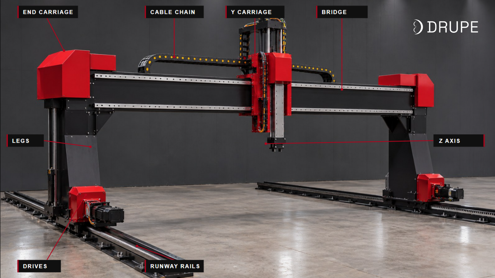
Strip the covers off any industrial gantry and you will find the same eight building blocks, scaled to the job.
Runway rails (X axis). Two parallel rail beams that run the length of the work area, either on the floor, on raised supports or on top of columns. Their straightness, parallelism and level set the ceiling for everything the gantry can achieve. On long machines they come in bolted modules, keyed and dowelled at the joints, like a long linear track.
End carriages or legs. The structures at each end of the bridge that ride on the runway rails. On a floor-running portal gantry these are the legs; on an elevated gantry they are short trucks sitting on the rail beams. Each one carries bearing blocks and, on driven sides, a motor and pinion.
Bridge (cross beam). The beam that spans the work area and carries the Y axis. Usually a fabricated box section or a stress-relieved welded beam, machined after welding so the Y guides sit true. The bridge is the single most important structural part: its stiffness decides how much the tool sags, twists and vibrates.
Y carriage. The plate that runs across the bridge and carries the Z axis, tool head or robot. On robotic gantries, the robot’s mounting pattern is machined into it.
Z axis. The vertical axis that brings the tool to the work. It can be a short slide with a torch height controller on a cutting machine, a telescopic or rack-driven mast on a heavy handling gantry, or no Z at all when an inverted robot does the reaching.
Drives and synchronisation. Servo motors, planetary gearboxes and rack and pinion on X and Y, with ballscrews or rack on Z. On portal gantries, X has a motor on each side, synchronised electronically. The next section covers this in detail.
Cable and energy chains. One chain along X, another along Y, sometimes a third on Z. They carry power, encoder and signal cables, torch leads, gas, air and coolant. As on linear tracks, an undersized or badly routed chain is one of the most common causes of downtime.
Controls and safety. The CNC or PLC, servo drives, limit switches and over-travel stops on every axis, anti-collision on the tool, and guarding around the work area: fences, light curtains or laser scanners where people load parts.
Any gantry datasheet that quotes envelope and speed without naming the bridge section, guides, drive and synchronisation method is leaving out the parts that decide how well it will actually cut, weld or place.
Drive mechanisms compared
| Configuration | How it is built | Typical span | Stiffness | Best for | Trade-offs |
|---|---|---|---|---|---|
| Cantilever | Beam supported and driven from one side only; the other side is open. | Up to about 2 to 3 m | Lower; tip deflection grows quickly with reach | Compact cutting machines, welding booms, cells where one side must stay open for loading | Reach and payload are limited; vibration at the free end shows up in cut or weld quality |
| Floor-running portal (double-column) | Two legs ride on two floor rails, joined by a bridge on top. | About 2 to 8 m, more on heavy builds | High | Plasma and oxyfuel plate cutting, large welding stations, heavy handling | Rails on the floor take space and need a good foundation; loading usually from the ends or sides |
| Elevated (overhead) gantry | Rails sit on columns or a steel frame above the work; the bridge runs on top. | About 3 to 10 m and beyond | High, if the support structure is stiff | Inverted robots, overhead pick-and-place, palletising, machine tending | Needs a tall, rigid support frame and good anchoring; overhead loading must be planned around it |
| Single-rail with outrigger | One precision driven rail on one side; the other side rolls on a simple support rail. | About 2 to 5 m | Medium | Cost-sensitive cutting and marking where accuracy needs are moderate | The undriven side can lag; less suited to high acceleration or heavy tools |
Which gantry configuration is best for you?
Match the shape of the work to the structure. Pick the row that sounds like your job.
For heavy fabrication, most gantries you will specify are either floor-running portals (cutting and large welding) or elevated gantries (inverted robots and overhead handling). Both rely on a driven rail on each side, which is why synchronisation matters so much.
Drives and synchronisation: keeping the bridge square
Every axis on a gantry uses one of the drives covered in our linear tracks guide: rack and pinion, ballscrew, toothed belt or linear motor. On industrial gantries the choice usually settles quickly. The harder question is how the two sides of the bridge are kept moving together.
| Axis | Usual drive | Why |
|---|---|---|
| X (along the runway) | Rack and pinion, one per side | Scales to long travel in bolted modules and handles the full moving mass of the bridge |
| Y (across the bridge) | Rack and pinion; toothed belt on light, fast gantries | Spans of several metres rule out ballscrews; belts suit light pick-and-place |
| Z (vertical) | Ballscrew on short strokes, rack and pinion on long or heavy masts | Ballscrews give fine control near the work; racks handle long strokes and heavy grippers |
Vertical axes need one extra thing: a holding brake on the motor or a counterbalance. If power is lost, an unbraked Z axis drops whatever it is holding.
Gantry synchronisation
On a portal or elevated gantry, the bridge is driven from both ends. There are three ways to keep those ends together.
| Method | How it works | Where it fits | Watch out for |
|---|---|---|---|
| Mechanical shaft | One motor drives a cross shaft that turns pinions on both sides. | Short spans and older or low-cost machines | Shaft twist and backlash grow with span; skew creeps in over time |
| Dual drive, electronic gantry (master and slave) | A servo motor on each side; the controller locks them together in software and corrects any difference in position. | Most modern cutting machines and robotic gantries | Needs a controller with a proper gantry function and careful tuning |
| Dual drive with independent feedback | Same as above, plus separate scales or encoders on each rail to measure true position on both sides. | Wide spans and high-accuracy work | Higher cost; worth it when squareness tolerance is tight |
The term to know is yaw (or skew): the angle the bridge makes when one side leads the other. Yaw throws off squareness, loads the guides sideways and wears the rack. A good gantry measures the difference between the two sides continuously and stops the machine if it exceeds a set limit, before anything binds.
On a plate cutting machine, dual drive is what lets a gantry cut square corners on a 3 metre plate at full speed. It is one of the first lines to look for on a cutting gantry’s spec sheet.
Types of gantries by application
The same building blocks (runway, bridge, carriage, drives, controls) show up in very different jobs. The application decides the configuration, the stiffness and the controller far more than any catalogue family does.
1. Cutting gantries
The most common gantry in heavy fabrication. A portal gantry runs along a cutting bed, carrying one or more plasma or oxyfuel torches, sometimes a bevel head. The controller follows the nested part program; the gantry’s job is to hold the programmed speed and path accurately across the whole plate. See our Plasma vs Oxyfuel comparison for how the process choice affects the machine.
What matters here: dual drive synchronisation, smooth motion at cutting speed, protection of rails and racks from slag and fume, and a bed wide enough for your largest plate plus loading clearance.
2. Welding gantries
Used when the weld seams are long, spread across a large part or need to be reached from above: box girders, PEB beams, rail car underframes, ship panels, tank and vessel sections. The gantry carries welding heads (often SAW or MIG/MAG tractors) or a welding robot over a fixture.
What matters here: steady low-speed motion for consistent travel speed, stiffness against the weight and reaction of welding heads and wire feeders, and spatter-proof cable chains and covers.
3. Robotic gantries (inverted robots)
A six-axis robot is mounted upside down on the Y carriage, sometimes with a Z axis above it. The gantry moves the robot across a large area; the robot does the fine work. Because the robot hangs from above, it can reach both sides and the top of a large part without walking around it, and the floor stays clear for fixtures and cranes.
What matters here: carriage and bridge stiffness against the robot’s dynamic loads, integration of gantry axes into the robot controller as external axes, and dress pack routing across two moving axes.
4. Material handling and pick-and-place gantries
Overhead XYZ gantries that move parts between stations: loading and unloading machines, stacking cut parts, palletising, moving heavy components between process steps. Here the tool is a gripper, vacuum lifter or magnet, and the gantry mostly goes to taught positions.
What matters here: payload including gripper and part, cycle time, Z stroke and braking, and robustness in dirty, high-duty environments. Precision needs are usually modest.
5. Machine tending and process gantries
Gantries that load CNC machines, presses or test stations, and gantries that carry other process tools: dispensing, inspection cameras, marking, painting, routing. These tend to be lighter and faster, closer in build to Cartesian robots.
What matters here: speed, repeatability at the pick and drop points, and clean integration with the machine’s own controls.
Precision, stiffness and deflection: what the numbers mean
A gantry inherits the three precision numbers of a linear track (positioning accuracy, repeatability and straightness) on every axis. It then adds three of its own, and these are the ones buyers most often forget to ask about.
Squareness. How close to 90 degrees the X and Y axes are. On a cutting gantry, poor squareness turns rectangles into parallelograms; on a 3 metre part, a small angle error becomes millimetres at the far corner. It is usually stated as an error over a length, for example millimetres per metre.
Bridge deflection. How much the beam sags when the carriage and payload sit in the middle of the span. A steel beam’s sag rises steeply with span: double the span with the same section and the sag goes up roughly eight times. That is why wider gantries need much deeper, heavier bridges, not just longer ones.
Dynamic stiffness. How much the structure vibrates and how fast it settles after a move. A gantry can be accurate standing still and still leave ripples on a cut edge or a weld if the bridge rings every time the torch changes direction. Stiffness and a well-tuned drive matter more than top speed.
Typical ranges by application
| Application | Positioning accuracy | Repeatability | What drives it |
|---|---|---|---|
| Plasma or oxyfuel plate cutting gantry | ±0.2 to ±0.5 mm over the bed | ±0.05 to ±0.1 mm | Dual-drive rack and pinion, bridge stiffness, squareness setup |
| Robotic welding or cutting gantry | ±0.2 to ±0.5 mm | ±0.1 mm class | Gantry structure plus the robot's own accuracy; seam tracking often closes the gap |
| Welding gantry with SAW or MIG heads | ±0.5 to ±1 mm | ±0.2 mm | Low-speed smoothness matters more than absolute accuracy |
| Heavy pick-and-place or palletising | ±1 mm or looser | ±0.2 to ±0.5 mm | Taught positions; grippers and guides absorb the rest |
| Light Cartesian robot (dispensing, inspection) | ±0.05 to ±0.1 mm | ±0.01 to ±0.02 mm | Short spans, belt or ballscrew drives, light payloads |
These are typical industry ranges for well-built machines, not guarantees. Always check the supplier's measured values for your envelope and payload.
Why over-specifying is a trap
The same rule from our linear tracks guide applies: repeatability should be about ten times better than the process tolerance you actually care about. A plasma kerf is 2 to 4 mm wide and cut parts typically need ±0.5 mm or so. A gantry holding ±0.05 mm repeatability is already well inside that. Paying for inspection-grade accuracy on a 6 metre cutting gantry adds a heavier bridge, finer guides and a more expensive foundation, with no visible change in the parts.
Where to spend instead: stiffness. A stiff bridge with honest accuracy figures will cut and weld better than a lighter one with impressive numbers measured at rest.
How to specify a gantry
Give a supplier the ten items below and you will get a quote built for your job. Give them “length”, “width” and “payload” and nothing else, and you will get the catalogue machine closest to those three numbers, followed by weeks of back-and-forth to make it fit your shop.
| Application | Positioning accuracy | Repeatability | What drives it |
|---|---|---|---|
| Plasma or oxyfuel plate cutting gantry | ±0.2 to ±0.5 mm over the bed | ±0.05 to ±0.1 mm | Dual-drive rack and pinion, bridge stiffness, squareness setup |
| Robotic welding or cutting gantry | ±0.2 to ±0.5 mm | ±0.1 mm class | Gantry structure plus the robot's own accuracy; seam tracking often closes the gap |
| Welding gantry with SAW or MIG heads | ±0.5 to ±1 mm | ±0.2 mm | Low-speed smoothness matters more than absolute accuracy |
| Heavy pick-and-place or palletising | ±1 mm or looser | ±0.2 to ±0.5 mm | Taught positions; grippers and guides absorb the rest |
| Light Cartesian robot (dispensing, inspection) | ±0.05 to ±0.1 mm | ±0.01 to ±0.02 mm | Short spans, belt or ballscrew drives, light payloads |
These are typical industry ranges for well-built machines, not guarantees. Always check the supplier's measured values for your envelope and payload.
Factors that often get missed
The building. An elevated gantry needs headroom for the columns, the bridge, the Z stroke and the part. Check it against the crane hook height in the bay, because a gantry and an overhead crane often have to share the same air.
Crane and forklift access. Plates and heavy parts usually arrive by crane. Make sure the gantry can park out of the way, and that the crane path does not cross the gantry’s cable chains or guarding.
Fume and slag. On cutting gantries, keep rails, racks and chains above or outside the slag zone, and plan the fume extraction (downdraft table or hood) with the gantry, not after it.
Future work. If longer plates or a second torch are likely within a few years, a slightly longer runway or a bridge sized for a second carriage costs far less now than a retrofit later.
The foundation is half the installation
A gantry is only as square and straight as the rails it runs on, and those rails are only as good as the floor beneath them. Floor-running portals need a level, reinforced foundation with the rail bed grouted at every anchor. Elevated gantries need columns anchored to a slab that will not settle unevenly. Laser alignment of both runways for straightness, level and parallelism at installation is not optional. A poor foundation is the most common reason a well-built gantry fails to hold its spec in service.